
Language switcher


Grigliatura
Si tratta di un processo essenziale finalizzato alla rimozione dei solidi grossolani presenti nel flusso delle acque. Offriamo una gamma completa di griglie meccaniche per la separazione dei solidi dalle acque reflue, caratterizzate da robustezza, facilità di manutenzione e alta efficienza operativa.
Applicazioni
Grigliatura acque e scarichi municipali
Grigliatura trattamento bottini
Grigliatura acque e scarichi industriali
| Luce di grigliatura | Larghezza canale | Altezza canale | |
|---|---|---|---|
| Sistemi di grigliatura grossolana per canale | 10-50 mm | 500-2000 mm | 1500-5000 mm |
| Sistemi di grigliatura FINE per canale | 3 & 6 mm | 300-2000 mm | 1500-5000 mm |
| Sistemi di grigliatura FINE INSTALLATI FUORI CANALE | 3 & 6 mm | 300-2000 mm | 1500-5000 mm |
Sistemi di grigliatura GROSSOLANA per canale
Modelli
EM32A
Pettine a movimento completamente meccanico con catene fuori acqua
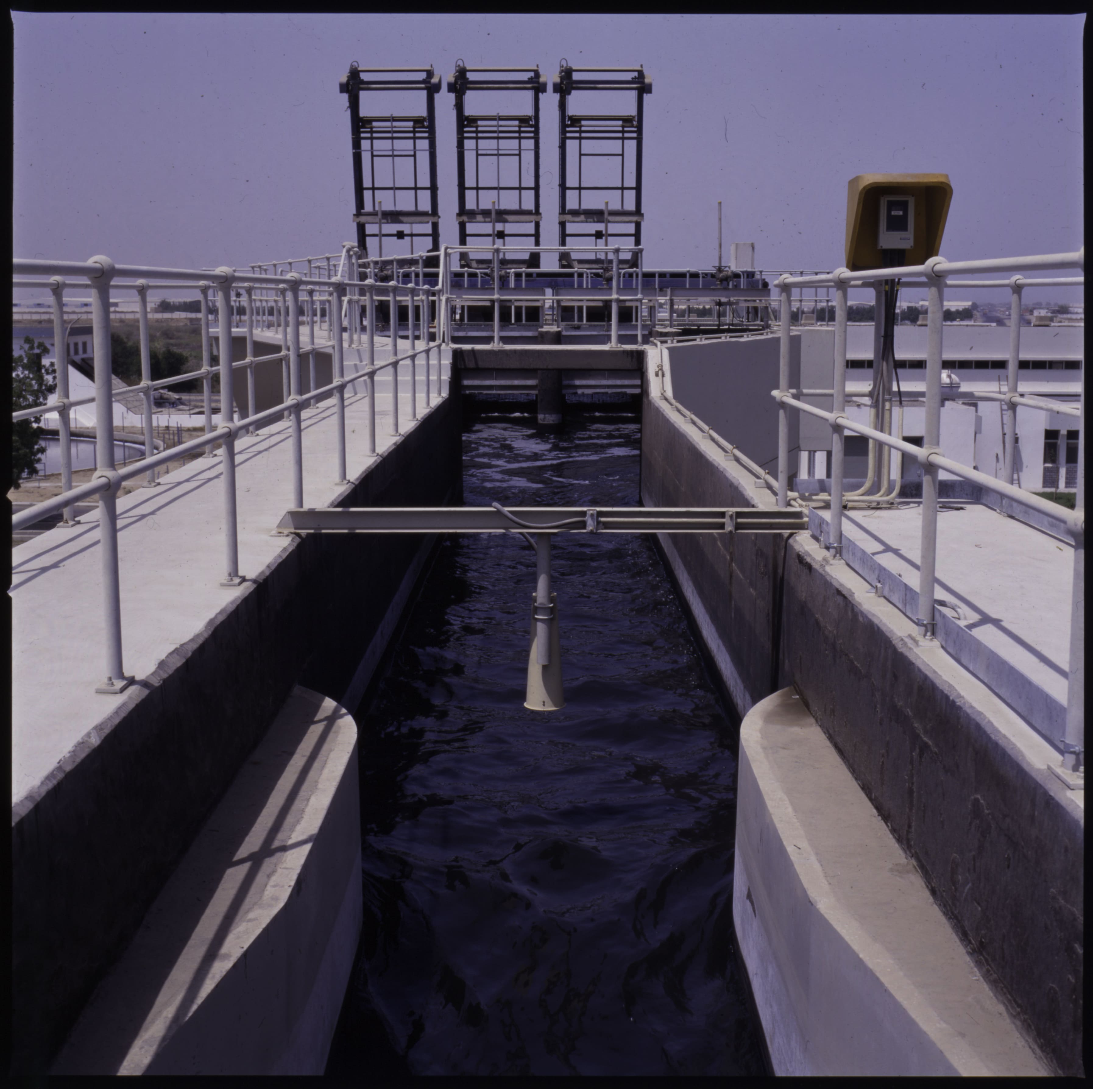
EM32A – GRIGLIA VERTICALE CON CATENE FUORI ACQUA
| Applicazione | Grigliatura di acque reflue civili e industriali |
| Caratteristiche | La macchina è composta da una griglia fissa e da un pettine pulitore mobile azionato da catene posizionate fuori acqua. |
| Funzionamento | I solidi grossolani vengono intercettati dalla griglia. Il grigliato viene rimosso dal pettine mobile e scaricato in sommità, fuori acqua. Il pettine è guidato da due carrelli laterali, azionati da due catene di trascinamento. |
| Costruzione | Macchina compatta in acciaio zincato o inossidabile. La catena e tutte le parti in movimento sono sempre mantenute fuori acqua. |
| Installazione | In canale in calcestruzzo. |
| Larghezza del canale | Da 1000 a 2500 mm. |
| Grado di filtrazione | Da 20 mm a 80 mm. |
| Vantaggi | Catene e parti in movimento mantenute fuori acqua |
| Opzioni | Cella di carico per la misura dello sforzo del pettine pulitore, con allarme e/o blocco della griglia. Passerella e scala per l’accesso ai componenti meccanici posti in sommità. |
DESCRIZIONE DI FUNZIONAMENTO:
La macchina è comandata da un timer pausa-lavoro. Se il livello dell’acqua a monte della griglia supera una soglia prefissata, un sensore di livello può comandare il riavvio della macchina anche durante la fase di pausa. La macchina si arresta in pausa solo se il pettine ha raggiunto una determinata posizione fuori acqua e dopo che è avvenuto lo scarico. La macchina è azionata da un motoriduttore che solleva e abbassa il pettine. Durante la corsa di discesa il pettine pulitore rimane aperto fino al raggiungimento della posizione più bassa. Quando il pettine pulitore raggiunge il fondo del canale, la catena lo avvicina alla griglia. Durante la corsa di salita il pettine pulisce la griglia e trattiene al suo interno il grigliato. Prima che il pettine raggiunga la posizione superiore, un apposito dispositivo ne pulisce la parte interna e scarica il grigliato all’esterno in un cassone o su un nastro trasportatore. Nel punto più alto un finecorsa controlla il movimento del pettine.
DATI TECNICI E DIMENSIONALI NECESSARI PER UNA QUOTAZIONE
| 1.1 | Portata di progetto nel canale | :m³/h | |
| 1.2 | Portata massima nel canale | :m³/h | |
| 1.3 | Livello massimo dell’acqua a valle della griglia | :mm. | |
| 1.4 | Livello massimo dell’acqua a monte della griglia | :mm. | |
| 1.5 | Larghezza del canale | :mm. | |
| 1.6 | Altezza del canale | :mm. | |
| 1.7 | Altezza di scarico dal fondo del canale | :mm. | |
| 1.8 | Spaziatura libera tra le barre | :mm. |
È inoltre necessario specificare i materiali con cui verrà costruita la macchina
-
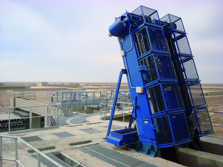
EM32A KSA AlKumrah C3023

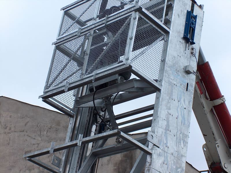
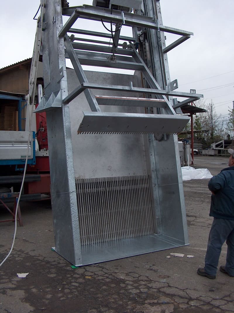
EM32H
Pettine a movimento meccanico/idraulico con catene fuori acqua
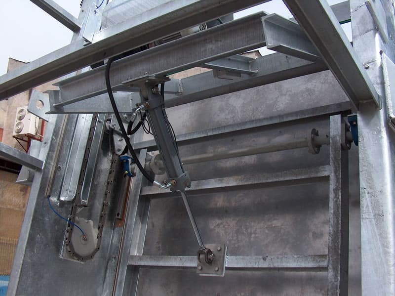
EM32H – GRIGLIA VERTICALE CON AZIONAMENTO IDRAULICO
| Applicazione | Grigliatura di acque reflue civili e industriali |
| Caratteristiche | La macchina è composta da una griglia fissa e da un pettine pulitore azionato da un cilindro idraulico. |
| Funzionamento | I solidi grossolani vengono intercettati dalla griglia. Il grigliato viene rimosso dal pettine mobile e scaricato in sommità, fuori acqua. Il pettine è guidato da due carrelli, azionati da due catene di trascinamento. L’innesto e il disinnesto del pettine sulla griglia sono eseguiti da un cilindro idraulico. |
| Costruzione | Macchina compatta in acciaio zincato o inossidabile. I componenti di azionamento sono sempre mantenuti fuori acqua. |
| Installazione | In canale in calcestruzzo. |
| Larghezza del canale | Da 1000 a 3500 mm. |
| Grado di filtrazione | Da 20 mm a 80 mm. |
| Vantaggi | Parti in movimento mantenute fuori acqua, elevata forza di penetrazione del pettine nella griglia fissa. |
| Opzioni | Cella di carico per la misura dello sforzo del pettine pulitore, con allarme e/o blocco della griglia. Passerella e scala per l’accesso ai componenti meccanici posti in sommità. |
DESCRIZIONE DI FUNZIONAMENTO:
La macchina è comandata da un timer pausa-lavoro. Se il livello dell’acqua a monte della griglia supera una soglia prefissata, un sensore di livello può comandare il riavvio della griglia anche durante la fase di pausa. La griglia si arresta in pausa solo se il pettine ha raggiunto una determinata posizione fuori acqua e dopo che è avvenuto lo scarico. La macchina è azionata da 1 motoriduttore per il sollevamento e l’abbassamento del pettine e da un cilindro idraulico, comandato da una centralina, per l’innesto e il disinnesto del pettine dalla griglia. Durante la corsa di discesa dei carrelli il pettine pulitore rimane aperto fino al raggiungimento della posizione più bassa. Quando il pettine pulitore raggiunge il fondo del canale, un finecorsa arresta la discesa. Il pistone idraulico innesta il pettine sulla griglia e, tramite un segnale, il motoriduttore riparte sollevando il pettine, ora innestato sulla griglia, fino al punto di scarico. Il pistone è dotato di due sensori di prossimità interni che consentono l’apertura o la chiusura completa. Durante la corsa di salita il pettine pulisce la griglia e trattiene al suo interno il grigliato. Prima che raggiunga la posizione superiore, un apposito dispositivo pulisce la parte interna del pettine e scarica il grigliato in un cassone o su un nastro trasportatore. Nel punto più alto un finecorsa arresta il motore che comanda il sollevamento della griglia e ne inverte il moto, avviando la corsa di discesa. Nel frattempo il cilindro idraulico allontana il pettine pulitore dalla griglia.
DATI TECNICI E DIMENSIONALI NECESSARI PER UNA QUOTAZIONE
| 1.1 | Portata di progetto nel canale | :m³/h |
| 1.2 | Portata massima nel canale | :m³/h |
| 1.3 | Livello massimo dell’acqua a valle della griglia | :mm. |
| 1.4 | Livello massimo dell’acqua a monte della griglia | :mm. |
| 1.5 | Larghezza del canale | :mm. |
| 1.6 | Altezza del canale | :mm. |
| 1.7 | Altezza di scarico dal fondo del canale | :mm. |
| 1.8 | Spaziatura libera tra le barre | :mm. |
È inoltre necessario specificare i materiali con cui verrà costruita la macchina
-
EM32H 11partic

-
EM32H 6partic
-
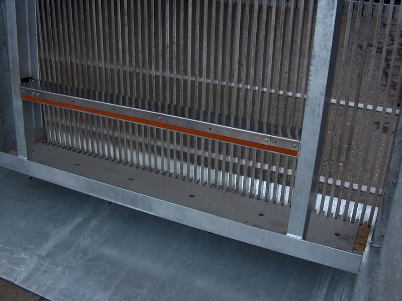
EM32H 7
-
EM32H 9partic
-
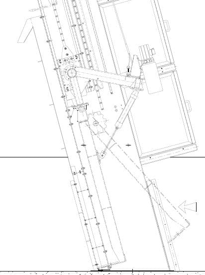
EM32H C04800-1
-
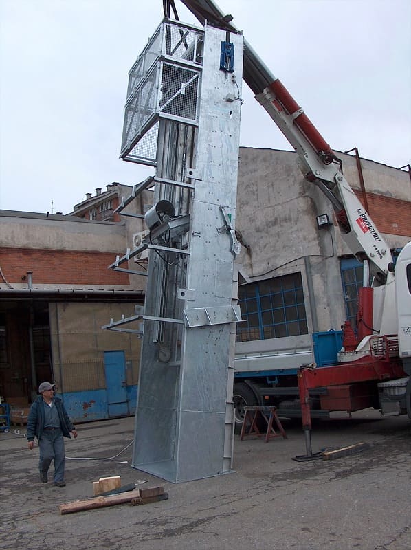
EM32H Pettine
-
EM32H 4
EM32C
Pettine a movimento completamente meccanico con catene immerse
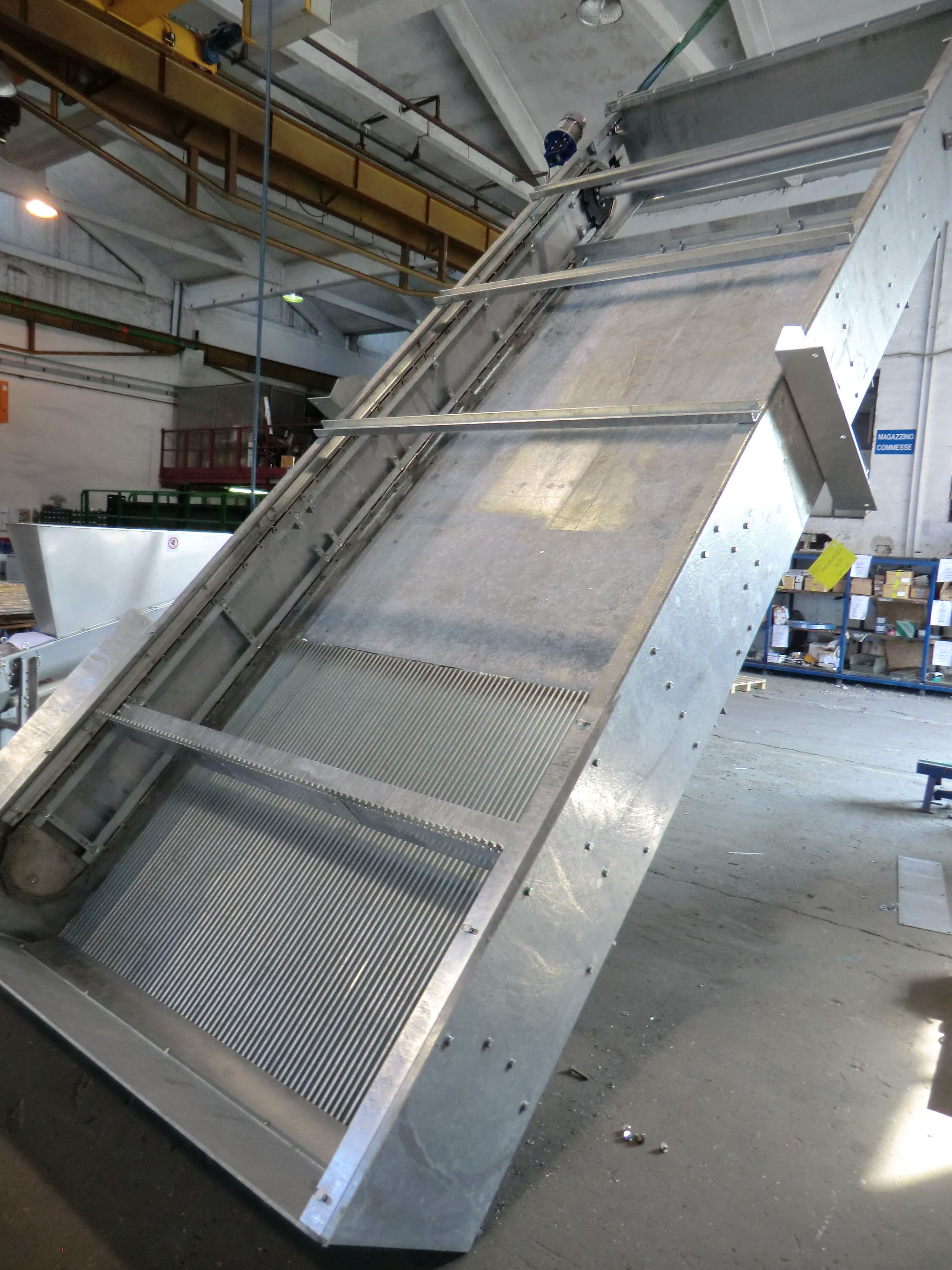
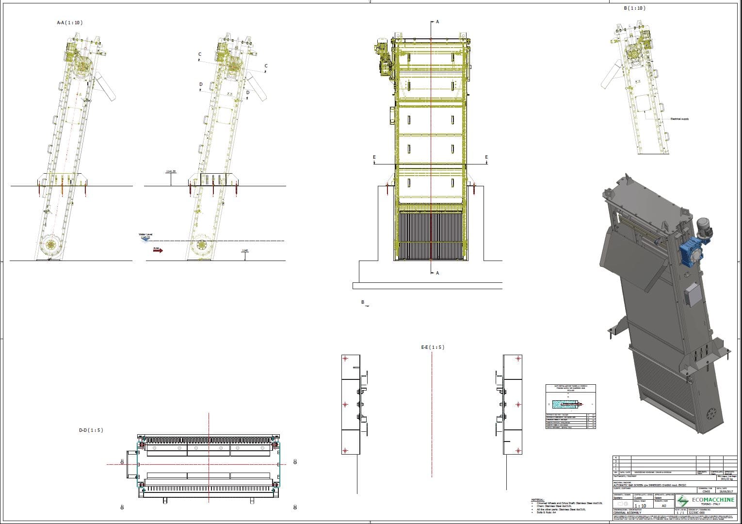
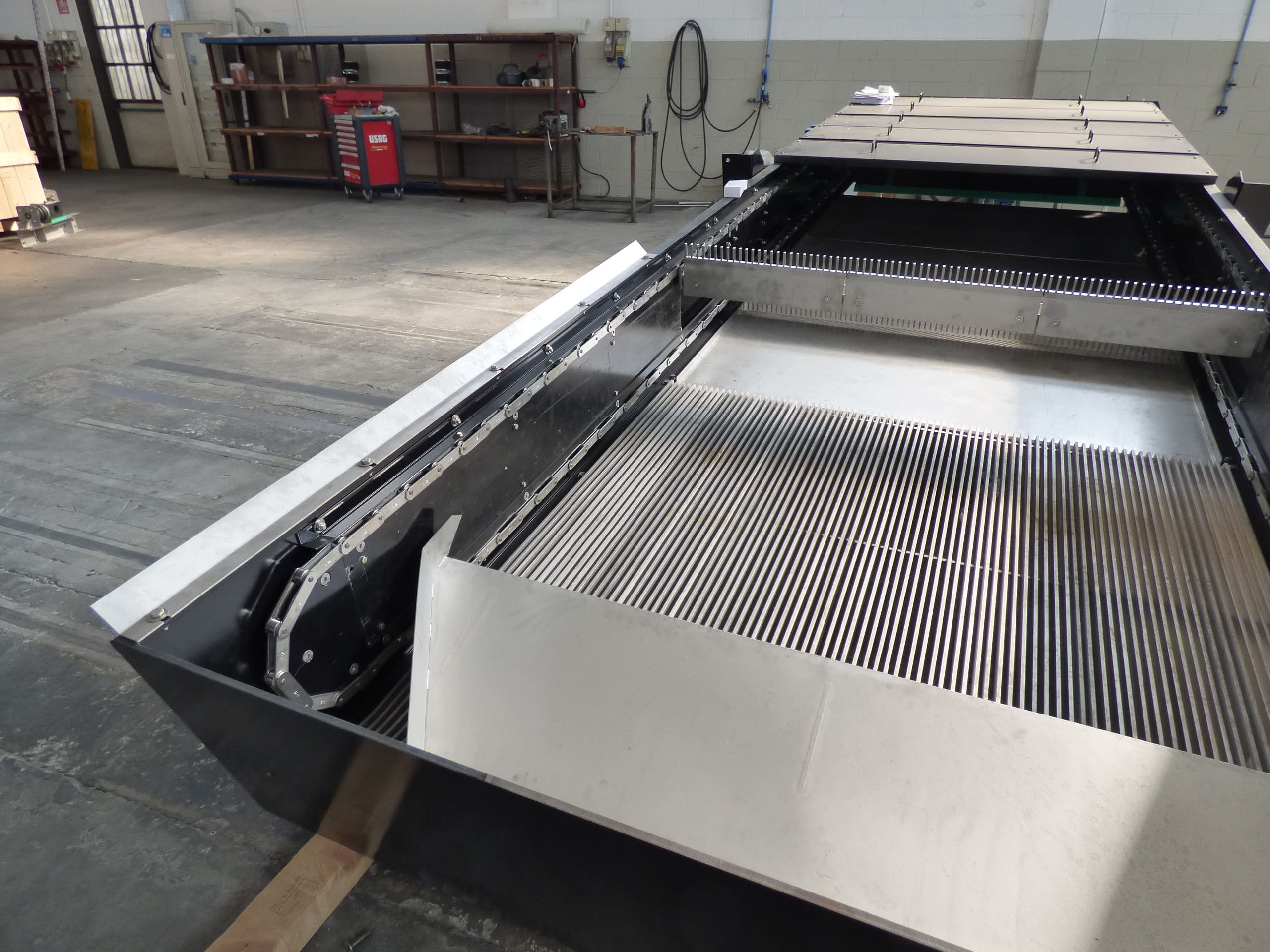
EM32C – GRIGLIA VERTICALE CON CATENE IMMERSE
| Applicazione | Grigliatura di acque reflue civili e industriali |
| Caratteristiche | La macchina è composta da una griglia fissa e da uno o più pettini pulitori azionati da catene |
| Funzionamento | I solidi grossolani vengono intercettati dalla griglia. Il grigliato viene rimosso da uno o più pettini pulitori azionati da una coppia di catene parzialmente immerse nel fluido da grigliare. |
| Costruzione | Macchina compatta in acciaio zincato o inossidabile. La catena è sempre in acciaio inossidabile. |
| Installazione | In canale in calcestruzzo. |
| Larghezza del canale | Da 500 a 1500 mm. |
| Grado di filtrazione | Da 10 a 80 mm. |
| Vantaggi | Costo contenuto, possibilità di impiegare più pettini pulitori. |
| Svantaggi | Difficoltà nella rimozione di solidi di dimensioni superiori a 300 mm. |
| Opzioni | Cella di carico per la misura dello sforzo del pettine pulitore, con allarme e/o blocco della griglia. |
DESCRIZIONE DI FUNZIONAMENTO
La macchina è comandata da un timer pausa-lavoro. Se il livello dell’acqua a monte della griglia supera una soglia prefissata, un sensore di livello può comandare il riavvio della macchina anche durante la fase di pausa. La macchina si arresta in pausa solo se il pettine ha raggiunto una determinata posizione fuori acqua e dopo che è avvenuto lo scarico. La macchina è azionata da un motoriduttore che solleva e abbassa il pettine. Durante la corsa di discesa il pettine pulitore rimane aperto fino al raggiungimento della posizione più bassa. Quando il pettine pulitore raggiunge il fondo del canale, la catena lo avvicina alla griglia. Durante la corsa di salita il pettine pulisce la griglia e trattiene al suo interno il grigliato. Prima che il pettine raggiunga la posizione superiore, un apposito dispositivo ne pulisce la parte interna e scarica il grigliato all’esterno in un cassone o su un nastro trasportatore. Nel punto più alto un finecorsa controlla il movimento del pettine.
DATI TECNICI E DIMENSIONALI NECESSARI PER UNA QUOTAZIONE
| 1.1 | Portata di progetto nel canale | :m³/h |
| 1.2 | Portata massima nel canale | :m³/h |
| 1.3 | Livello massimo dell’acqua a valle della griglia | :mm. |
| 1.4 | Livello massimo dell’acqua a monte della griglia | :mm. |
| 1.5 | Larghezza del canale | :mm. |
| 1.6 | Altezza del canale | :mm. |
| 1.7 | Altezza di scarico dal fondo del canale | :mm. |
| 1.8 | Spaziatura libera tra le barre | :mm. |
È inoltre necessario specificare i materiali con cui verrà costruita la macchina
-
EM32C C5455
-
EM32C Italy Avezzano C5286

-
EM32C Kuwait Napoli C5279
EM32OL
Pettine a movimento completamente idraulico

Lack of information...
EM32D
Pettine a movimento completamente meccanico con funi di sollevamento
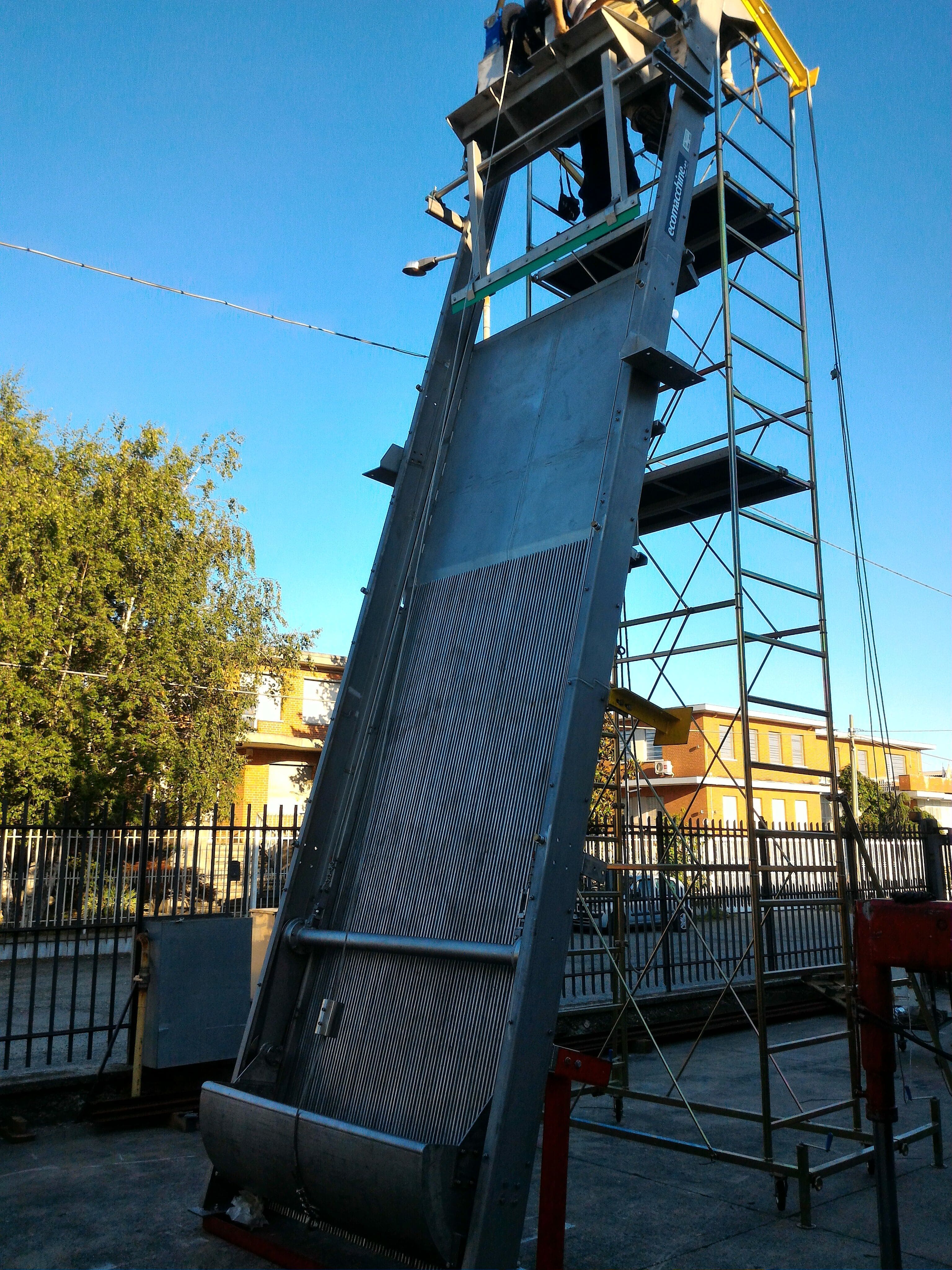
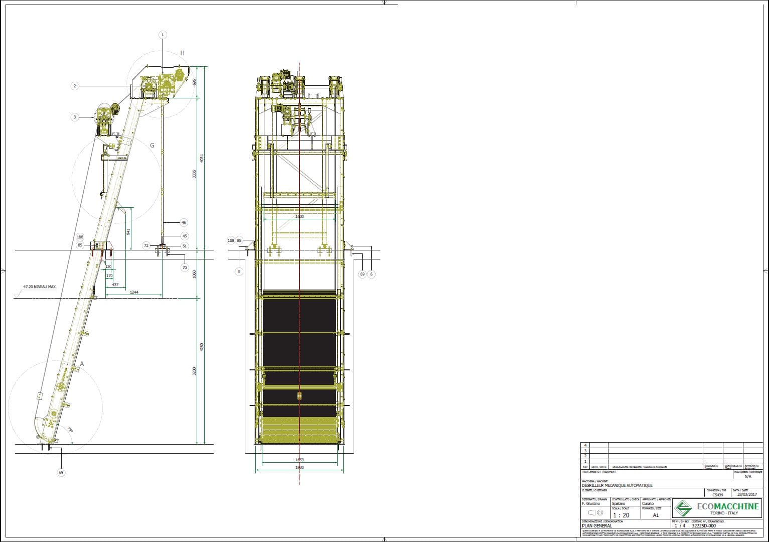
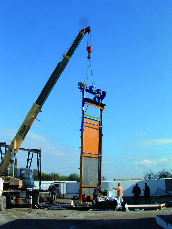
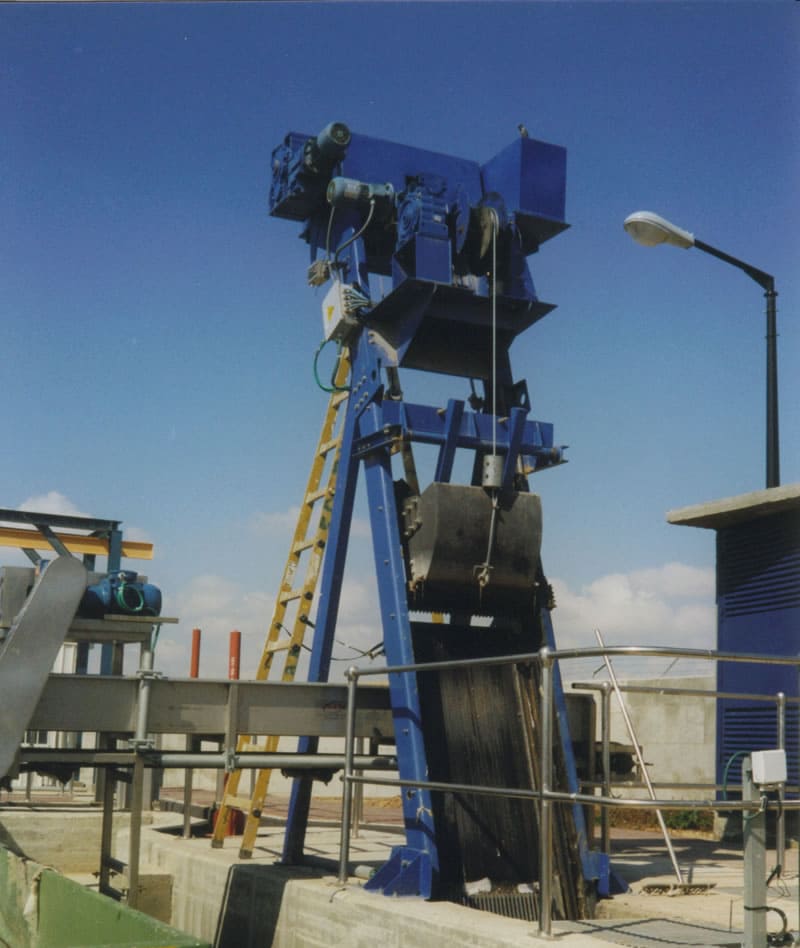
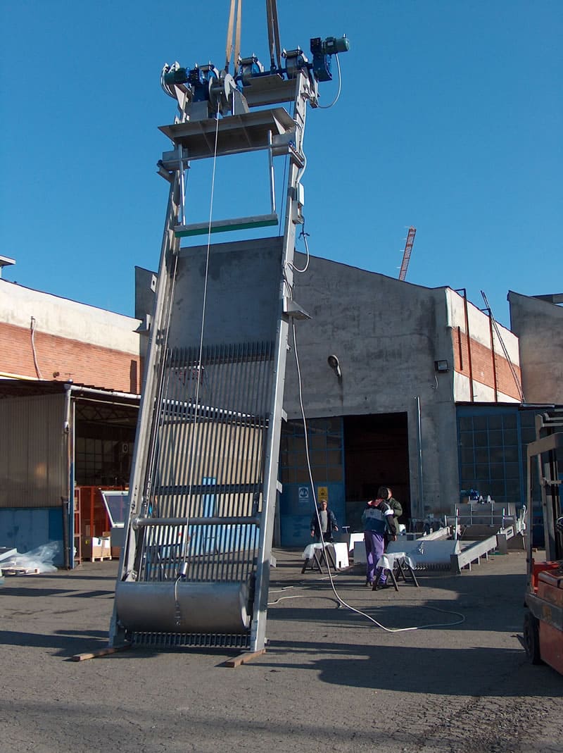
EM32D – GRIGLIA VERTICALE CON SISTEMA DI SOLLEVAMENTO A FUNI
| Applicazione | Grigliatura di acque reflue civili e industriali |
| Caratteristiche | La macchina è composta da una griglia fissa e da una benna mordente azionata da due gruppi di comando, uno per il movimento verticale e l’altro per l’apertura e la chiusura della benna. |
| Funzionamento | I solidi grossolani vengono intercettati dalla griglia. Il grigliato viene rimosso dalla benna mordente mobile e scaricato in sommità, fuori acqua. La benna è guidata da due carrelli, movimentati da due sistemi a funi (uno per il movimento verticale e l’altro per l’apertura e la chiusura). |
| Costruzione | Macchina compatta in acciaio zincato o inossidabile. I componenti di azionamento sono sempre mantenuti fuori acqua |
| Installazione | In canale in calcestruzzo. |
| Larghezza del canale | Da 1000 a 3000 mm. |
| Grado di filtrazione | Da 15 a 100 mm. |
| Vantaggi | Adatta a canali molto profondi, con presenza di sabbia sul fondo e solidi di grandi dimensioni. |
| Svantaggi | Non adatta a canali di piccole dimensioni. |
| Opzioni | Cella di carico per la misura dello sforzo del pettine pulitore, con allarme e/o blocco della griglia. Passerella e scala per l’accesso ai componenti meccanici posti in sommità. |
DESCRIZIONE DI FUNZIONAMENTO:
La macchina è comandata da un timer pausa-lavoro. Se il livello dell’acqua a monte della griglia supera una soglia prefissata, un sensore di livello può comandare il riavvio della griglia anche durante la fase di pausa. La macchina si arresta in pausa solo se la benna ha raggiunto una determinata posizione fuori acqua e dopo che è avvenuto lo scarico. La macchina è azionata da 2 motoriduttori: uno comanda il sollevamento del pettine pulitore, l’altro comanda il gruppo che innesta e disinnesta il pettine dalla griglia. Nella parte superiore del gruppo di comando sono presenti 3 tamburi: 2 laterali e 1 centrale. I tamburi sono azionati da un motoriduttore e avvolgono/svolgono le funi che sollevano e abbassano il pettine pulitore. Il secondo motoriduttore aziona una puleggia che avvolge e svolge la fune centrale, provocando l’avvicinamento e l’allontanamento della benna dalla griglia. Durante la corsa di discesa del carrello la benna rimane aperta fino al raggiungimento della posizione più bassa. Quando la benna appoggia sul fondo, la fune di sollevamento si allenta e un finecorsa (collegato alla tensione della fune) arresta il motoriduttore. Il senso di rotazione del 1° motoriduttore viene invertito e si attiva il secondo motoriduttore, che avvolge la fune centrale in modo che la benna si innesti sulla griglia. Avviene quindi la corsa di salita, durante la quale la benna pulisce la griglia e trattiene al suo interno il grigliato. Prima che la benna raggiunga la posizione superiore, un apposito dispositivo ne pulisce la parte interna e scarica il materiale in un cassone o su un nastro trasportatore. Nel punto più alto un finecorsa arresta il motore che comanda il sollevamento della griglia e ne inverte il moto, avviando la corsa di discesa. Nel frattempo il 2° motoriduttore aziona il tamburo centrale, allontanando il pettine pulitore dalla griglia. La corsa di discesa avviene con la benna mantenuta distante dalla griglia.
DATI TECNICI E DIMENSIONALI NECESSARI PER UNA QUOTAZIONE
| 1.1 | Portata di progetto nel canale | :m³/h |
| 1.2 | Portata massima nel canale | :m³/h |
| 1.3 | Livello massimo dell’acqua a valle della griglia | :mm. |
| 1.4 | Livello massimo dell’acqua a monte della griglia | :mm. |
| 1.5 | Larghezza del canale | :mm. |
| 1.6 | Altezza del canale | :mm. |
| 1.7 | Altezza di scarico dal fondo del canale | :mm. |
| 1.8 | Spaziatura libera tra le barre | :mm. |
È inoltre necessario specificare i materiali con cui verrà costruita la macchina
-
EM32D 000-R0
-
EM32D C04487-Tunisia
-
EM32D Lehavim1
-
EM32D
-
EM32D Tunisia Ghedir C5439-1
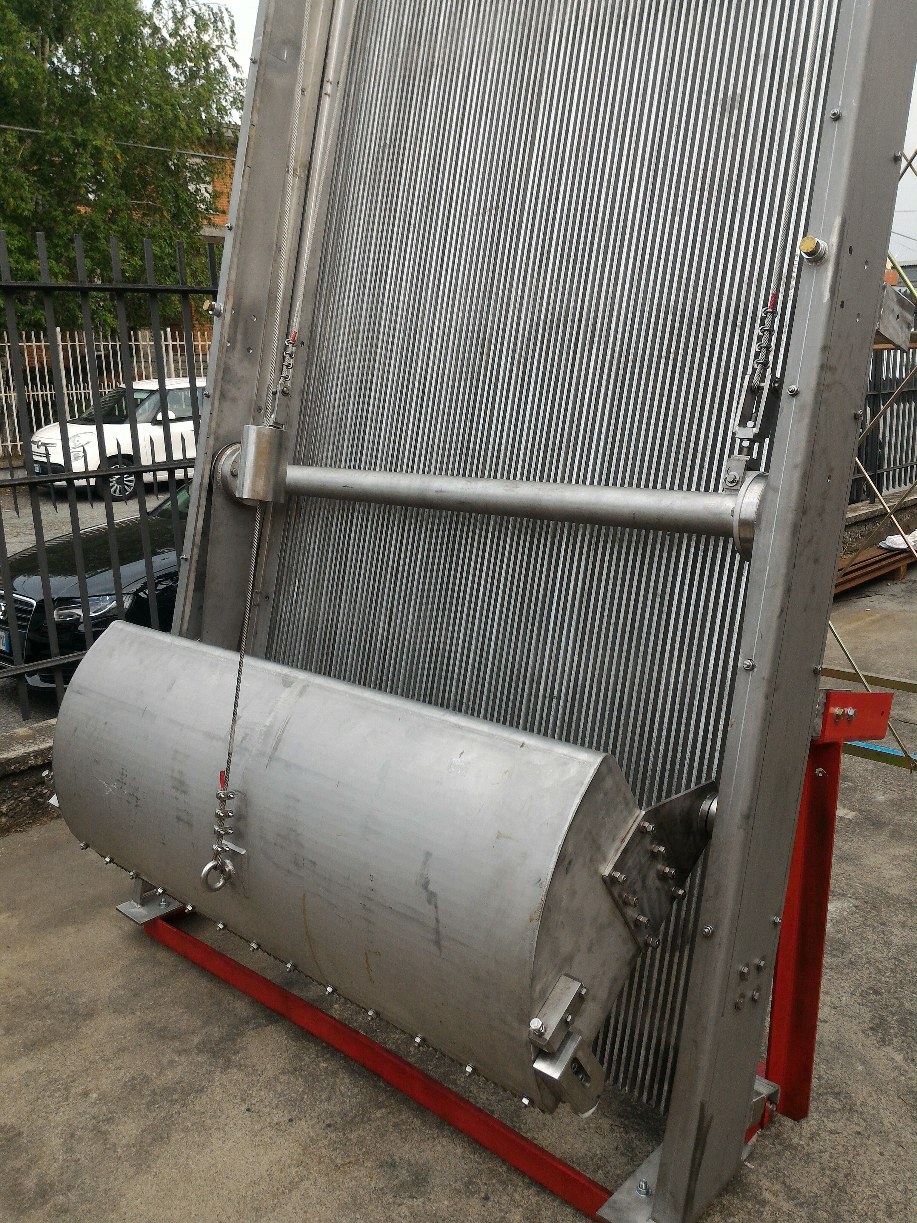
-
EM32D Tunisia Ghedir C5439-2

-
EM32D Tunisia Ghedir C5439
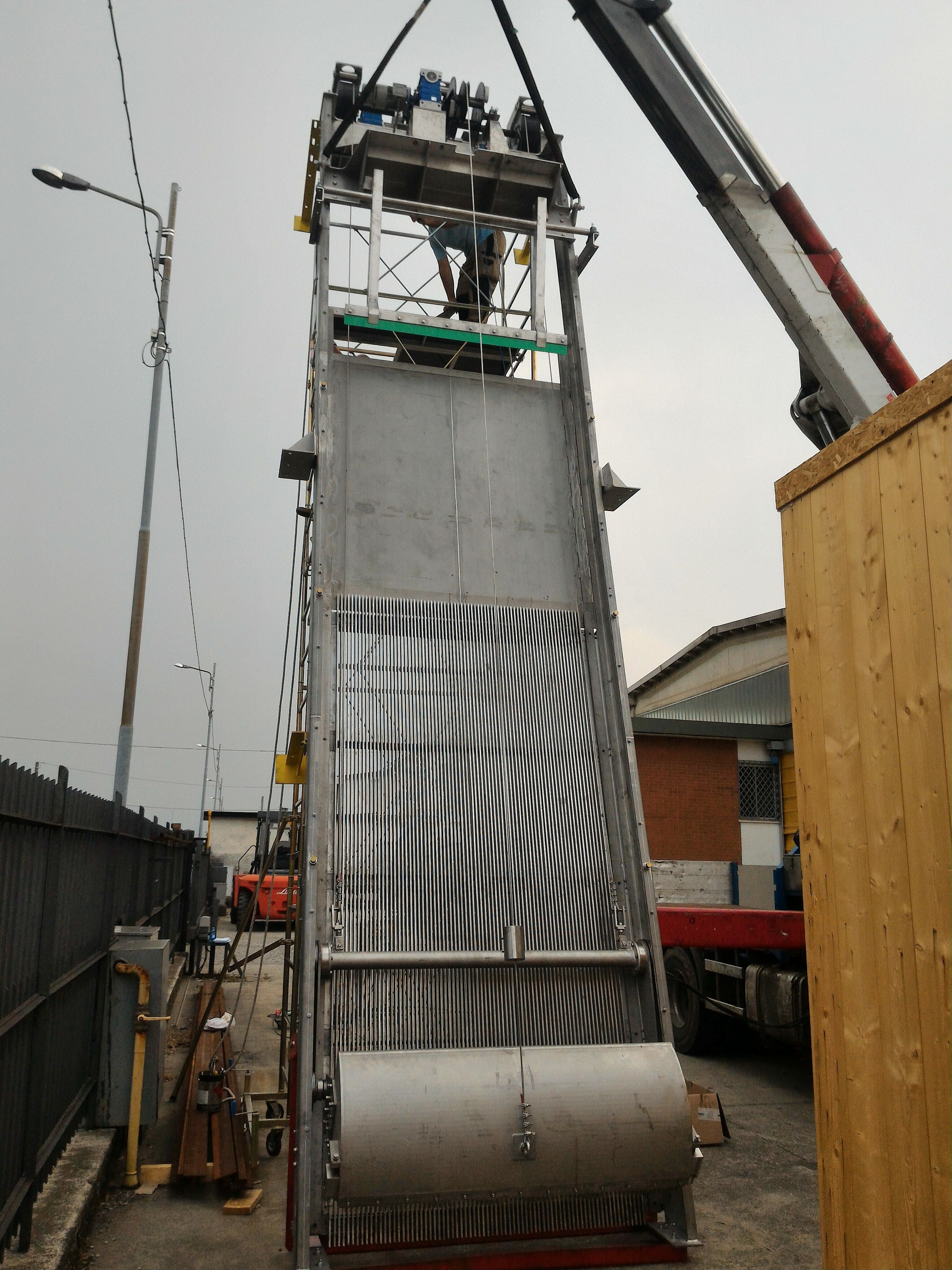
Sistemi di grigliatura FINE per canale
Modelli
EM31G
Griglia a nastro continuo con denti in plastica autopulenti
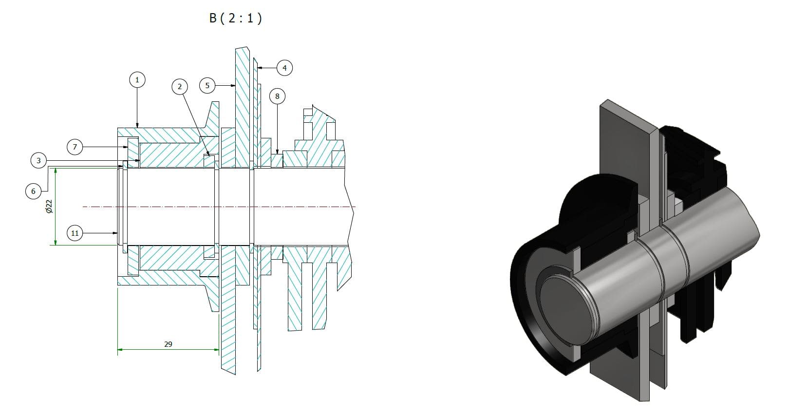
EM31G – GRIGLIA VERTICALE A NASTRO CONTINUO
| Applicazione | Grigliatura di acque reflue civili e industriali |
| Caratteristiche | La macchina è composta da un nastro filtrante con denti e ruote in resina acetalica e alberi in acciaio inossidabile, ed è dotata di una spazzola di pulizia e di un sistema di lavaggio. |
| Funzionamento | L’acqua contenente particelle in sospensione attraversa il nastro filtrante, depositandovi i solidi sospesi. Il grigliato viene sollevato e rimosso con l’ausilio di una spazzola rotante e di un sistema di lavaggio. |
| Costruzione | Macchina compatta in acciaio inossidabile. |
| Installazione | In canale in calcestruzzo. |
| Larghezza del canale | Da 300 a 2000 mm. |
| Grado di filtrazione | 3 o 6 mm. |
| Vantaggi | Filtrazione continua, adatta anche ad acque contenenti materiale fibroso. |
| Svantaggi | Difficoltà nella rimozione di solidi di dimensioni superiori a 250 mm. |
| Opzioni | Giunto a slittamento con sensore di allarme. Doppia spazzola di pulizia motorizzata. |
DESCRIZIONE DI FUNZIONAMENTO
La macchina è comandata da un timer pausa-lavoro. Se il livello dell’acqua a monte della griglia supera una soglia prefissata, un sensore di livello può comandare il riavvio della macchina anche durante la fase di pausa. Il nastro filtrante solleva in continuo i solidi trattenuti e in sommità il grigliato viene ribaltato e scaricato, con l’ausilio del movimento reciproco dei denti, di una spazzola rotante e di due rampe di lavaggio che rimuovono ulteriormente il grigliato.
DETTAGLI COSTRUTTIVI
Ruote
Per evitare l’usura degli alberi portadenti, questa macchina è dotata di boccole di protezione montate alle estremità degli alberi, sulle quali ruotano le ruote. Le ruote sono in materiale plastico, prodotte in serie, economiche e facilmente sostituibili.
Guide
Le guide sono imbullonate al telaio e facilmente sostituibili.
DATI TECNICI E DIMENSIONALI NECESSARI PER UNA QUOTAZIONE
| 1.1 | Portata di progetto nel canale | :m³/h |
| 1.2 | Portata massima nel canale | :m³/h |
| 1.3 | Livello massimo dell’acqua a valle della griglia | :mm. |
| 1.4 | Livello massimo dell’acqua a monte della griglia | :mm. |
| 1.5 | Larghezza del canale | :mm. |
| 1.6 | Altezza del canale | :mm. |
| 1.7 | Altezza di scarico dal fondo del canale | :mm. |
| 1.8 | Spaziatura libera tra le barre | :mm. |
I materiali impiegati sono l’acciaio inossidabile per il telaio e gli alberi e la resina acetalica per i denti filtranti e le ruote.
-
EM31G 200
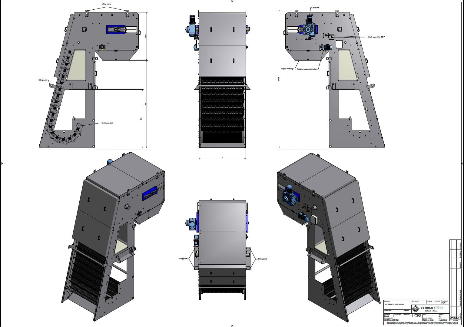
-
EM31G Ovada4
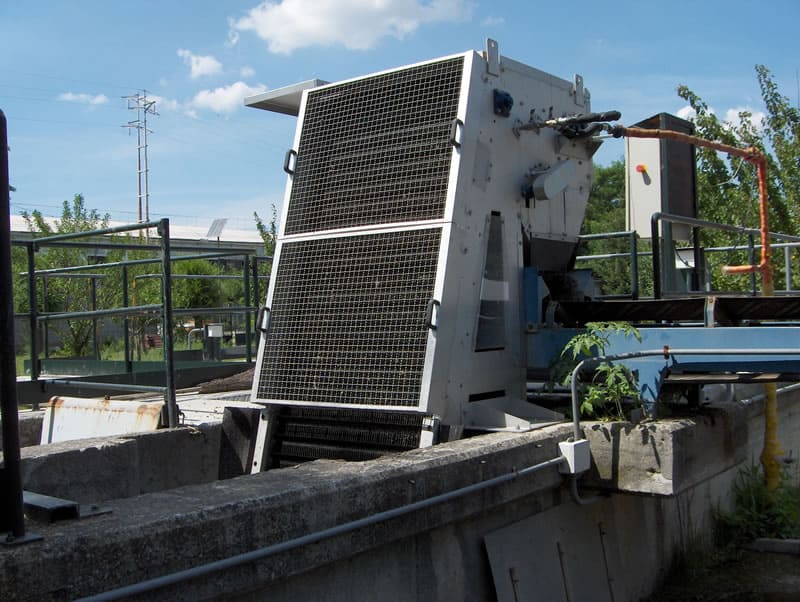
-
EM31G Ovada5
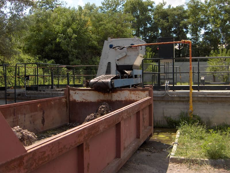
-
EM31G Rondella2

-
EM31G Tipico
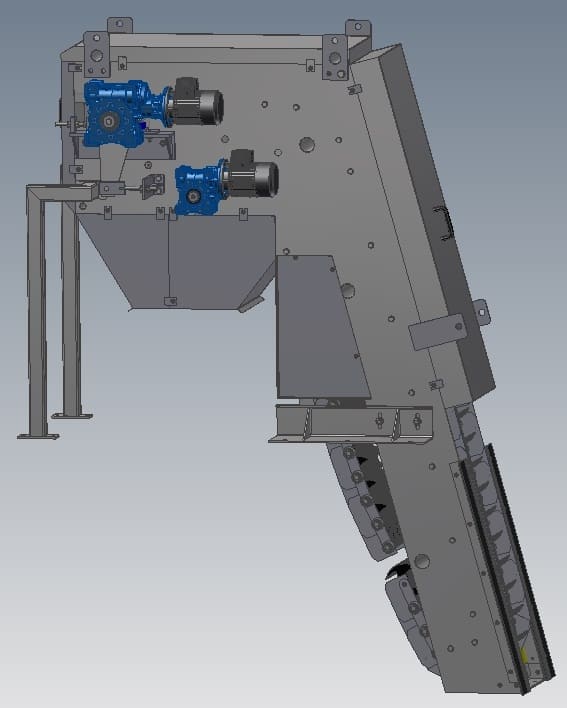
-
EM31G Acea-1
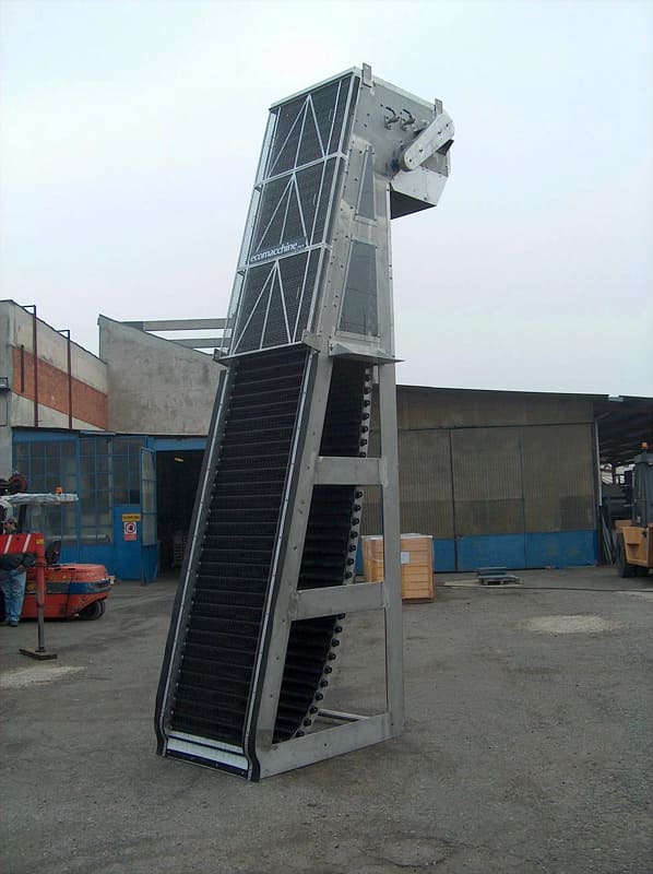
EM31C
Griglia a cestello fisso inclinato con coclea di pulizia e compattatore

EM31C – GRIGLIA INCLINATA A CESTELLO FISSO CON COMPATTATORE
| Applicazione | Grigliatura di acque reflue civili e industriali. |
| Caratteristiche | La macchina è composta da un cestello a barre trapezoidali, da una coclea di sollevamento e compattazione e da rampe di lavaggio. |
| Funzionamento | L’acqua contenente particelle in sospensione attraversa il cestello filtrante, depositandovi i solidi sospesi. Il grigliato viene scaricato in una coclea di sollevamento e compattazione. Il grigliato viene rimosso e lavato da 3 rampe di lavaggio. |
| Costruzione | Macchina compatta in acciaio inossidabile. |
| Installazione | In canale in calcestruzzo |
|
Larghezza del canale |
Da 600 a 2000 mm. |
| Grado di filtrazione | Da 0,25 a 6 mm. |
| Vantaggi | Filtrazione continua, adatta anche ad acque contenenti materiale fibroso. |
| Svantaggi | Difficoltà nella rimozione di solidi di dimensioni superiori a 250 mm. |
DESCRIZIONE DI FUNZIONAMENTO
La macchina è comandata da un timer pausa-lavoro. Se il livello dell’acqua a monte della griglia supera una soglia prefissata, un sensore di livello può comandare il riavvio della macchina anche durante la fase di pausa. L’acqua da trattare viene filtrata dalla griglia fissa; i solidi trattenuti vengono sollevati, compattati e scaricati da una coclea. Durante il sollevamento il grigliato viene sottoposto a lavaggio per rimuovere le sostanze organiche solubili.
DATI TECNICI E DIMENSIONALI NECESSARI PER UNA QUOTAZIONE
| 1.1 | Portata di progetto nel canale | :m³/h |
| 1.2 | Portata massima nel canale | :m³/h |
| 1.3 | Livello massimo dell’acqua a valle della griglia | :mm. |
| 1.4 | Livello massimo dell’acqua a monte della griglia | :mm. |
| 1.5 | Larghezza del canale | :mm. |
| 1.6 | Altezza del canale | :mm. |
| 1.7 | Altezza di scarico dal fondo del canale | :mm. |
| 1.8 | Spaziatura libera tra le barre | :mm. |
La griglia è realizzata in acciaio inossidabile con coclea in acciaio ad alta resistenza, a richiesta interamente in acciaio inossidabile
-
EM31C BarreCurve

-
EM31C
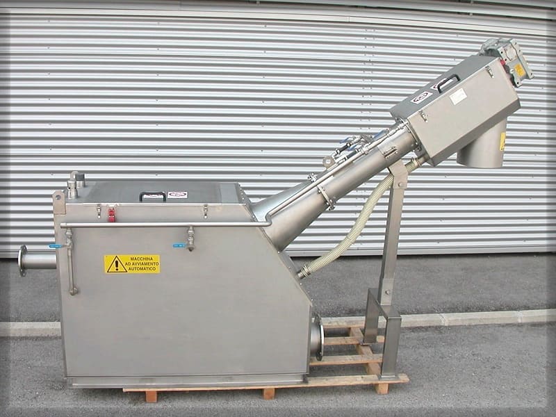
Sistemi di grigliatura FINE INSTALLATI FUORI CANALE
Modelli
EM79
Rotostrainer (griglia a tamburo rotante)
EM79 – ROTOSTRAINER
| Applicazione | Grigliatura di acque reflue civili e industriali. |
| Caratteristiche | La macchina è composta da un tamburo rotante |
| Funzionamento | I solidi grossolani vengono intercettati sulla superficie esterna del tamburo. Il grigliato viene rimosso da una lama raschiante e il tamburo viene pulito da una rampa di lavaggio posizionata al suo interno |
| Costruzione | Macchina compatta in acciaio inossidabile. |
| Installazione | Autoportante |
| Diametro del tamburo | 628 o 920 mm |
| Lunghezza del tamburo | Da 500 a 3000 mm |
| Grado di filtrazione | Da 0,25 a 3 mm. |
| Svantaggi | Spazzola di pulizia |
DESCRIZIONE DI FUNZIONAMENTO
La macchina è comandata da un timer pausa-lavoro. Se il livello dell’acqua nella vasca di alimentazione supera una soglia prefissata, un sensore di livello può comandare il riavvio della macchina anche durante la fase di pausa. L’acqua da trattare entra nel comparto di alimentazione e viene distribuita sull’intera superficie del tamburo. La filtrazione avviene dall’esterno verso l’interno del tamburo. L’acqua entrata nel tamburo esce dall’interno verso l’esterno del tamburo. In questo modo il tamburo di grigliatura si mantiene costantemente autopulente. I solidi grigliati sulla superficie esterna del tamburo vengono rimossi da una lama raschiante e, a richiesta, con l’ausilio di una spazzola motorizzata. L’alimentazione può avvenire a gravità o tramite pompa
DATI TECNICI E DIMENSIONALI
Tabella delle portate (m³/h) con SST = 200 ppm
| Modello | 0.25 | 0.5 | 0.75 | 1.0 | 1.25 | 1.5 | 2 | 2.5 | 3 |
| EM79-6005 | 45 | 80 | 105 | 125 | 140 | 155 | 180 | 195 | 210 |
| EM79-6006 | 55 | 95 | 125 | 150 | 170 | 190 | 210 | 235 | 250 |
| EM79-6007 | 65 | 110 | 150 | 180 | 200 | 220 | 250 | 280 | 300 |
| EM79-6008 | 75 | 125 | 170 | 205 | 230 | 255 | 290 | 320 | 340 |
| EM79-6010 | 90 | 160 | 215 | 260 | 290 | 320 | 370 | 405 | 430 |
| EM79-6015 | 135 | 240 | 325 | 395 | 450 | 490 | 555 | 610 | 650 |
| EM79-6020 | 180 | 300 | 435 | 530 | 590 | 650 | 750 | 820 | 870 |
| EM79-9030 | 435 | 740 | 980 | 1250 | 1450 | 1650 | 1850 | 2150 | 2350 |
EM100G
Sistema di filtrazione a nastro Ultrascreen
EM100G – ULTRASCREEN
| Applicazione | Grigliatura di acque reflue civili e industriali. |
| Caratteristiche | La macchina è composta da un nastro filtrante ad anello continuo |
| Funzionamento | I solidi grossolani vengono intercettati dal nastro e scaricati in un contenitore esterno. Il nastro viene spazzolato e lavato con acqua |
| Costruzione | Macchina compatta in acciaio inossidabile. |
| Installazione | Autoportante |
| Larghezza del nastro | 1200 – 2100 – 3000 mm |
| Grado di filtrazione | Da 150 micron a 2 mm. |
| Vantaggi | Adatta alla filtrazione di acque contenenti solidi con grassi, materiale fibroso e sostanze che tendono a intasare le tradizionali griglie a tamburo rotante |
| Opzioni | Lavaggio ad alta pressione |
DESCRIZIONE DI FUNZIONAMENTO
La macchina è comandata da un timer pausa-lavoro. A seconda dell’applicazione, la macchina può essere avviata da un sensore di livello dell’acqua nella vasca di alimentazione oppure da un sensore di flusso nella tubazione di alimentazione o di scarico. L’acqua da trattare entra nel comparto di alimentazione e viene distribuita sull’intera superficie del nastro. La filtrazione avviene a gravità; i solidi vengono trattenuti dal nastro e quindi rimossi da un sistema di spazzole rotanti motorizzate. Dopo lo scarico, il nastro viene lavato in continuo da un sistema di lavaggio ad acqua ad alta pressione. In questo modo il nastro si mantiene costantemente autopulente. L’alimentazione può avvenire a gravità o tramite pompa
DATI TECNICI E DIMENSIONALI NECESSARI PER UNA QUOTAZIONE
| 1.1 | Portata di alimentazione al filtro | : m³/hr | |||
| 1.1 | Solidi sospesi in ingresso | : p.p.m. | |||
| 1.2 | Dimensione minima dei solidi da separare | : micron | |||
| 1.3 | Modello applicabile | : EM | 100/1200 | 100/2100 | 100/3000 |
| 1.4 | Larghezza del nastro | : mm | 1200 | 2100 | 3000 |
| 1.5 | Velocità del nastro filtrante | : mt/min. | 1.6-8.5 | 1.6-8.5 | 1.6-8.5 |
| 1.6 | Apertura massima della maglia | : micron | |||
| Utenze richieste | |||||
| Acqua di lavaggio del nastro | |||||
| 1.7 | portata | : m3/hr | 1.2 | 2 | 3 |
| 1.8 | prevalenza | : Bar | 20 | 20 | 20 |
| Aria compressa | |||||
| 1.9 | portata | : lt/min. | 250 | 250 | 250 |
| 1.10 | pressione | : Bar | 7 | 7 | 7 |
| Utenze elettriche | |||||
| 1.11 | Azionamento del nastro | : Kw | 0.55 | 0.75 | 1.5 |
| 1.12 | Spazzola di pulizia | : Kw | 0.37 | 0.37 | 0.37 |
| 1.13 | Pompa dell’acqua ad alta pressione | : Kw | 4 | 5.5 | 7.5 |
| 1.14 | Compressore d’aria | : Kw | 2.2 | 2.2 | 2.2 |
| 1.15 | Pompa sommergibile per il ritorno dell’acqua di lavaggio | : Kw | 0.55 | 0.75 | 1.1 |
Accessori
Modelli
EM49
Coclea di trasporto per grigliato
EM49 – COCLEA DI TRASPORTO
| Applicazione | Trasporto di fango disidratato o grigliato. |
| Caratteristiche | La macchina è composta da una coclea che ruota all’interno di una canala. |
| Costruzione | Acciaio zincato o inossidabile. |
| Modelli | EM49 A1 Coclea piana con albero EM49 A2 Coclea inclinata fissa con albero EM49 A3 Coclea inclinata brandeggiabile con albero EM49 A4 Coclea piana D/S con albero EM49 B1 Coclea piana senza albero EM49 B2 Coclea inclinata fissa senza albero EM49 B3 Coclea inclinata brandeggiabile senza albero EM49 B4 Coclea piana D/S senza albero |
Per quotare una coclea di trasporto sono necessarie le seguenti informazioni
| 1.1 | Lunghezza | : m | |
| 1.2 | Diametro della coclea | : mm | 500 |
| 1.3 | Altezza di carico | : m | |
| 1.4 | Altezza di scarico | : m | |
| 1.5 | Portata da trasportare | : kg/h |
EM62
Nastro trasportatore per grigliato
EM62 – NASTRI TRASPORTATORI
| Applicazione | Trasporto di fango disidratato o grigliato. |
| Caratteristiche | La macchina è composta da un nastro in movimento che trasporta i solidi. |
| Costruzione | Acciaio zincato o inossidabile. |
| Modelli | EM62 A Piano EM62 B Inclinato fisso EM 62 C Inclinato brandeggiabile EM 62 D A collo di cigno |
| Dispositivi di sicurezza | Interruttore di emergenza a fune posizionato lungo i bordi del nastro trasportatore. |
Per quotare un nastro trasportatore sono necessarie le seguenti informazioni
| 1.1 | Lunghezza | : m | |
| 1.2 | Larghezza del nastro | : mm | 500 |
| 1.3 | Altezza di carico | : m | |
| 1.4 | Altezza di scarico | : m | |
| 1.5 | Portata da trasportare | : kg/h |
EM56
Compattatore a coclea per grigliato
EM56F – COMPATTATORE A COCLEA
| Applicazione | Trasporto e compattazione del grigliato |
| Caratteristiche | La macchina è composta da una coclea e da un gruppo di compattazione |
| Funzionamento | Il grigliato viene convogliato dalla coclea nel gruppo di compattazione; l’acqua separata ritorna nel canale |
| Costruzione | Macchina compatta in acciaio inossidabile. |
| Installazione | Fuori canale |
| Diametro della canala | 200 mm |
| Lunghezza della coclea | Variabile |
DESCRIZIONE DI FUNZIONAMENTO
Il grigliato viene convogliato dalla coclea nella zona di compattazione, dotata di cestello drenante e lavaggio intermittente, dove viene compattato e scaricato. L’acqua drenata ritorna nel canale di scarico.
DATI TECNICI E DIMENSIONALI
| 1.1 | Larghezza della canala | : mm. | 225 |
| 1.2 | Diametro esterno della coclea | : mm. | 180 |
| 1.3 | Diametro interno della coclea | : mm. | 105 |
| 1.4 | Portata | : m3/h | 2 |
| 1.5 | Inclinazione | : ° | 5° |
| 1.6 | Velocità della coclea | : r.p.m. | 28 |
| 1.7 | Altezza di scarico del grigliato | : mm. | |
| 1.8 | Lunghezza della coclea | : mm. | |
| 1.9 | Lunghezza totale | : mm. | |
| 1.10 | Acqua di lavaggio | : m³/h | 1-2 |
| 1.11 | Potenza installata | : Kw. | 1.5 |
| 1.12 | Tensione di alimentazione | : V-ph-Hz | 380-3-50 |
| 1.13 | Protezione del motore | : IP | 55 |
Il materiale normalmente impiegato per la costruzione è l’acciaio inossidabile.
EM86
Compattatore oleodinamico
EM86 – COMPATTATORE A PISTONE IDRAULICO
| Applicazione | Trasporto e compattazione del grigliato |
| Caratteristiche | La macchina è composta da una camera di carico con pistone, da un tubo di compattazione e scarico e da una centralina idraulica |
| Funzionamento | Il grigliato viene raccolto nel cilindro; il pistone si muove avanti e indietro e durante la corsa di avanzamento compatta il grigliato nel tubo di scarico. |
| Costruzione | Macchina compatta in acciaio inossidabile. |
| Installazione | Fuori canale |
| Diametro del pistone | 250 mm o 350 mm |
DATI TECNICI E DIMENSIONALI NECESSARI PER UNA QUOTAZIONE
| 1.1 | Pressa di convogliamento: | |||
| 1.1.1 | Portata | : m³/h. | 1.8 | 2.7 |
| 1.1.2 | Diametro del cilindro | : mm. | 250 | 350 |
| 1.1.3 | Pressione specifica massima | : kg/cm² | 15 | 10 |
| 1.1.4 | Dimensioni della bocca di carico | : mm. | 500×350 | 600×450 |
| 1.1.5 | Flangia di uscita del materiale compattato | : DN | 250 | 350 |
| 1.1.6 | Flangia di scarico dell’acqua separata | : “ | 2 | 2 |
| 1.1.7 | Materiale di costruzione | : AISI | 304 | 304 |
| 1.2 | Centralina idraulica: | |||
| 1.2.1 | Potenza installata | : kW | 4 | 5.5 |
| 1.2.2 | Portata della pompa | : l/min | 8 | 10 |
| 1.2.3 | Capacità del serbatoio dell’olio | : l | 60 | 60 |
| 1.2.4 | Pressione massima di esercizio | : BAR | 200 | 200 |
| 1.3 | Cilindro idraulico: | |||
| 1.3.1 | Alesaggio | :mm | 80 | 100 |
| 1.3.2 | Corsa | :mm | 700 | 700 |
| 1.3.3 | Diametro dello stelo | :mm | 40 | 60 |
| 1.3.4 | Forza a 200 bar | : kg. | 7,400 | 9,700 |
CALCOLO DELLE PERDITE DI CARICO
Rientrano fra i fenomeni di efflusso rigurgitato anche quelli di attraversamento delle griglie, formate da barre allungate nella direzione della corrente. Le barre possono essere di varia sezione e inclinate di un diverso angolo (α) sul piano orizzontale (Fig. FG1). La perdita di carico attraverso una griglia viene determinata utilizzando la formula di KIRSHMER: 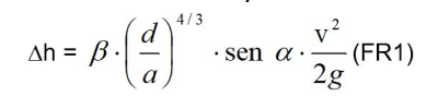 dove: – v : velocità dell’acqua in assenza della griglia; – α: angolo di inclinazione della griglia rispetto all’orizzontale; – d : spessore delle barre; – a: luce libera tra le barre; – β: coeff. di forma funzione della sezione della barra, come indicato in figura. In sostanza, il valore:
 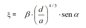 rappresenta una perdita di carico che provoca un “rigurgito” a monte o a valle della griglia, a secondo che si tratti di corrente lenta o veloce.
Il risultato vale per griglia pulita; per griglia intasata la perdita di carico aumenta notevolmente.
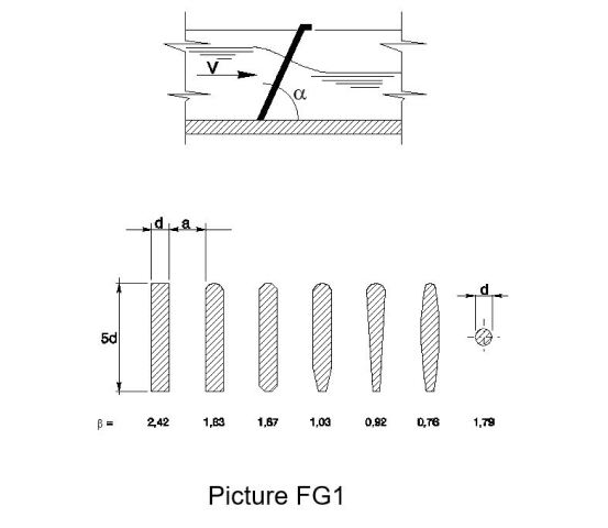
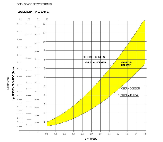 Valori indicativi delle perdite di carico attraverso griglie di diversa luce libera di passaggio con inclinazione di 60°
EM31C BarreCurve
 EM31G 200
 EM31G Ovada4
 EM31G Ovada5
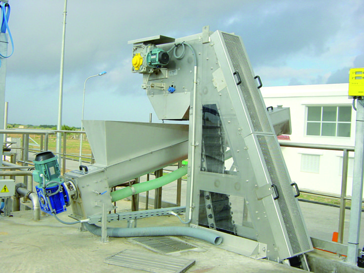 EM31G100 Dégrilleur
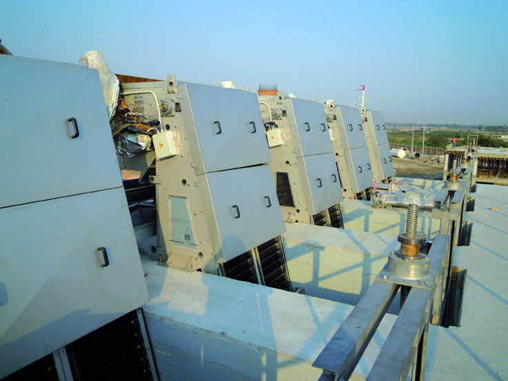 EM31G100 Messico
EM31G Rondella2
EM31G100 Messico
EM31G Rondella2
 EM31G Tipico
EM32A KSA AlKumrah C3023
EM31G Tipico
EM32A KSA AlKumrah C3023
 EM32C C5455
EM32C Italy Avezzano C5286
EM32C C5455
EM32C Italy Avezzano C5286
 EM32C Kuwait Napoli C5279
 EM32D 000-R0
 EM32D C04487-Tunisia
 EM32D Lehavim1
 EM32D
EM32D
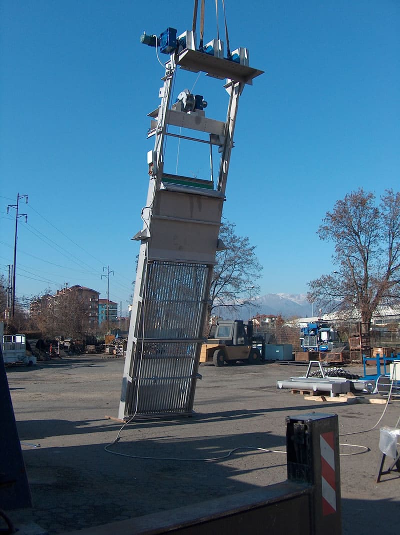 EM32D1
 EM32D Tunisia Ghedir C5439-1
EM32D Tunisia Ghedir C5439-2
EM32D Tunisia Ghedir C5439-1
EM32D Tunisia Ghedir C5439-2
 EM32D Tunisia Ghedir C5439
EM32H 11partic
EM32D Tunisia Ghedir C5439
EM32H 11partic
 EM32H 6partic
 EM32H 7
 EM32H 9partic
 EM32H C04800-1
 EM32H Pettine
 EM31C
EM31C
 EM31G Acea-1
 EM32H 4