
Language switcher


Circular clarifiers
Svolgono un ruolo cruciale nel trattamento delle acque reflue. Questi dispositivi sono progettati per ridurre il volume dei fanghi, concentrandone la parte solida e diminuendo il contenuto di acqua, così da migliorare l’efficienza dei trattamenti successivi e ridurre i costi operativi e di smaltimento.
Gli ispessitori possono essere di diversi tipi, come gravitazionali o meccanici, ciascuno con caratteristiche specifiche per adattarsi a diverse esigenze impiantistiche.
Application
Municipal water and wastewater sedimentation and thickening
Industrial water and wastewater sedimentation and thickening
Peripheral drive scraping and suction type clarifiers and thickeners
Models
EM10C
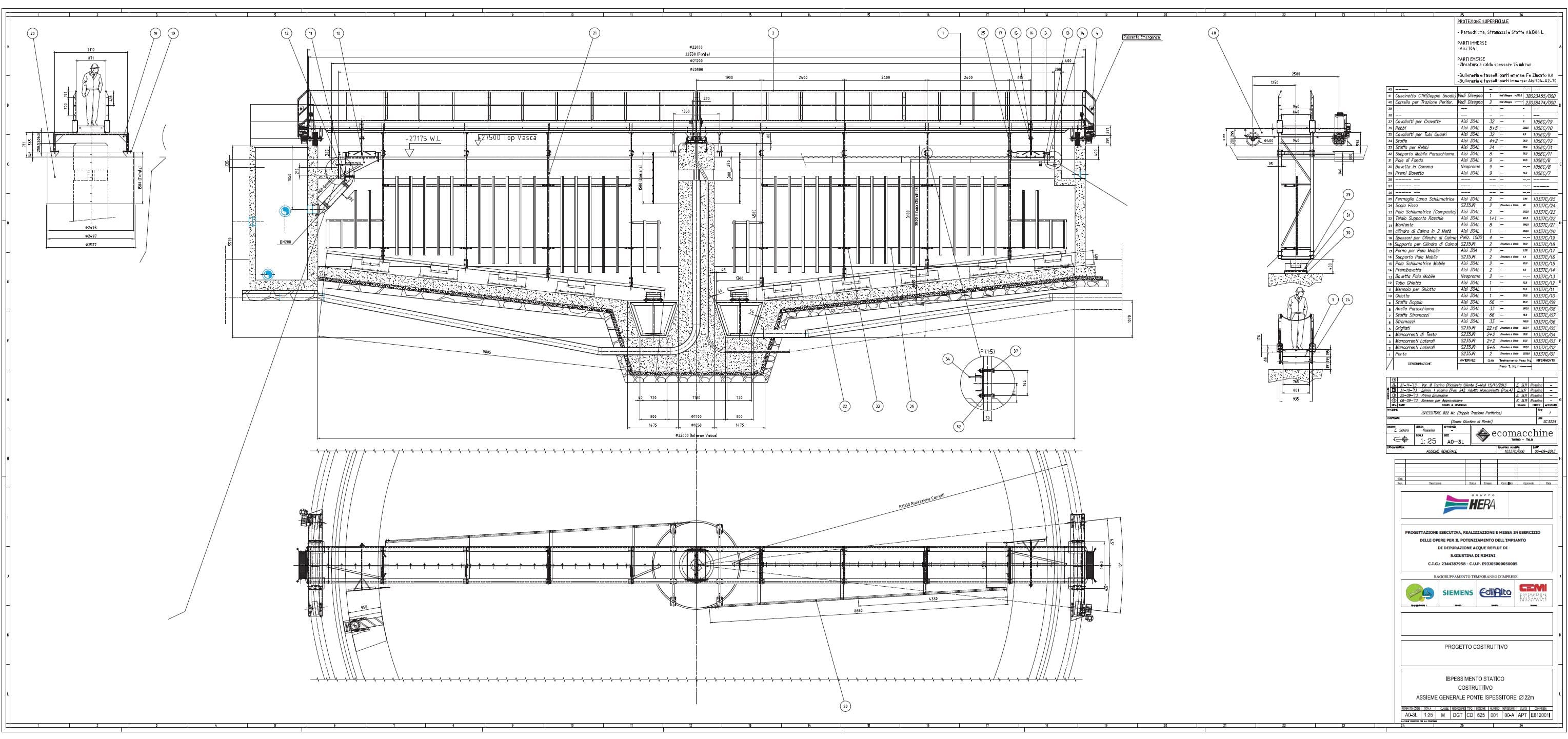
Ispessitore a doppia trazione periferica
Lack of information...
EM17
Peripheral drive clarifier
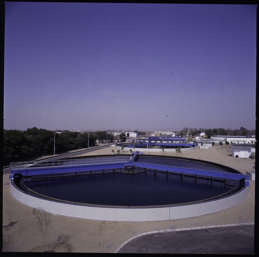
EM17 – PERIPHERAL DRIVE SCRAPER BRIDGE FOR CIRCULAR TANK
| Application | Clarifying of primary and secondary waste water |
| Tipi di macchine | Simple peripheral drive R+1/3 peripheral drive Double peripheral drive |
| Characteristics | The equipment consists of a diffusion drum and rotating bridge which draws the scrapers. |
| Operation | The water to be treated flows into the diffusion drum where the kinetic energy is slowed down, the sedimentable solids settle on the tank bottom and are conveyed towards to central drain well by the bottom scrapers. |
| Materials | Hot dip galvanized carbon steel or Stainless steel |
| Installation | In a concrete tank |
| Tank diametre | From 8 to 60 m. |
| Optionals | Scum removal system |
PRINCIPLES OF SIZING
Hydraulic sizing (process) The sizing of the diffusion drum is based on the following parametres: • influent flow rate • piping diametre The water coming out of the diffusion drum to the sedimentation zone must have a very low kinetic energy in order to guarantee a good separation and settling of the solids. Moreover, the bottom scrapers must have a continuous and logarythmic profile in order to successfully convey the sludge into the central well in less than a complete rotation of the shaft, 270° (¾).
Mechanical Sizing The sizing of the bottom scraper is based on the type of sludge to be evacuated from the tank bottom. The central column, the trolleys and the scrapers are designed to bear a stress of 20 Kg. per linear metre. The torque to transmit is calculated by: T [kgm] = r² x K r is the tank radius K is the load on the scrapers per linear metre (20 kg for biological clarifiers) The trolleys drive unit shall be capable of transmitting a 1.8 higher torque than the design value.
Torque limiting device (dynamometric cell) The dynamometric cell measures the torque transmited by the drive unit. This value is evident directly on the instrument and allows to evaluate the stresses on the gearbox during rotation. The device is equipped with limit switches set at two different torque values, one for alarm and one for the machine shutdown.
Selection of the electric motor The electric motor size is selected so that, in case of shutdown, its static torque is lower than the one which can be borne by each downstream unit. For this reason the electric motor is usually very small. Exuberant motors may cause, in case of shutdown, serious damages to the structures if the torque limiting device fails to intervene or if it is not properly connected.
Example of calculation: Tank diametre 20 m. K = 20 Scrapers peripheral speed 1,5 m/min Slow shaft rpm 0,047 Torque r² x K = 10² x 20 = 2000 kgm (in case of radial scrapers, the torque is halved) so the drive unit shall be designed to transmit a 1.8 higher torque
Electric motor To transmit a torque of 1000 kgm, the thrust of each trolley must be 1000 : 5 = 200 kg. If the wheel diameter is 300 mm., then the torque on the shaft is 200 x 0.15 (wheel radius) = 30 kgm. Therefore, at a speed of about 1.5 rpm, 62 watt are necessary. If we hypothize a drive unit output of 60%, the electric motor shall have a power of 113 watt. Normally it is difficult to find electric motors which are smaller than 0,18 kw – 180 watt. If the selected motor has got a power of 180 watt, in case of shutdown it might give a 2.6 times higher power for a few seconds, i.e. 468 watt. The torque transmitted by the motor to the wheel slow shaft, with a drive unit (on the trolleys) output of 60%, would be equal to 48 kgm., the thrust of the trolley would be 320 kg. and the torque 3200 kgm. for each trolley (total 3200 kgm.) Therefore the central column must be designed to bear a torsion stress (in case of shutdown) of 3200 kgm.
-
EM17 AlKhumrah

-
EM17 BeniMessous
EM29C
Peripheral drive clarifier
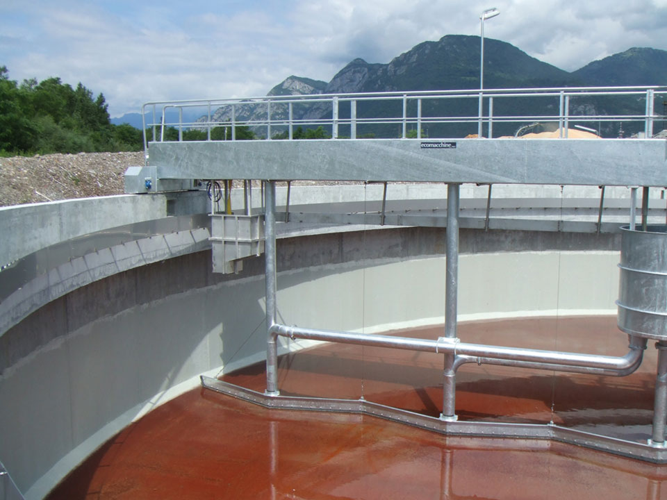
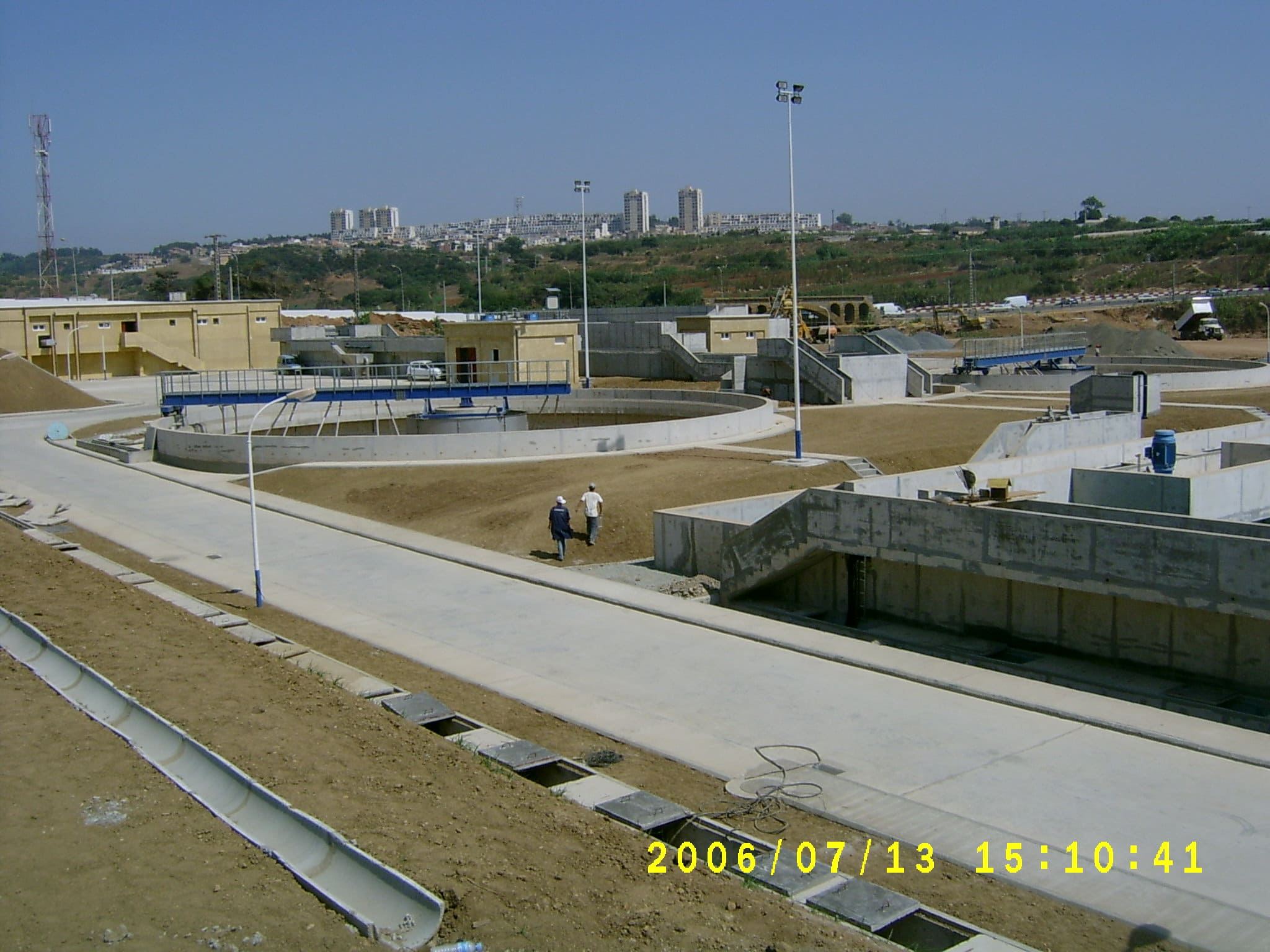
EM29 – PERIPHERAL DRIVE – SUCTION TYPE SCRAPER BRIDGE FOR CIRCULAR TANK
| Application | Clarifying of secondary waste water |
| Types | Simple peripheral drive R+1/3 peripheral drive Double peripheral drive |
| Characteristics | The equipment consists of a rotating bridge with scrapers equipped with suction pipes. |
| Operation | The water to be treated flows into the diffusion drum where the kinetic energy is slowed down, the sedimentable solids settle on the tank bottom and are sucked by the suction pipes equipped with regulating telescopic valves. |
| Materials | Hot dip galvanized carbon steel or Stainless steel |
| Installation | In a concrete tank |
| Tank diametre | From 8 to 60 m. |
| Optionals | Scum removal system |
PRINCIPLES OF SIZING
Sludge suction unit sizing. For the project of the sludge suction unit we have to make sure that the sludge is quickly removed from the tank bottom because if it tends to settle or get too thick for staying in the tank for a too long time, it may happen that: • a part of the recycled sludge returns to the oxidation tank when it is no more fresh and this will affect the treatment efficiency • a shortage of dissolved oxygen may cause a leakage of sludge in the effluent
Mechanical Sizing Same principles as described for the Peripheral drive scraper bridge mod. EM17.
OPERATION DESCRIPTION
The bottom of the suction scraper bridge tank is flat and the suction pipes, sized according to sludge recycle flow rate, are placed at a distance which does not exceed 3 m. The sludge is conveyed towards the suction pipe by V-shaped scrapers which make the flowing of the sludge towards the piping much easier. Each suction pipe is equipped with a telescopic valve to regulate the flow into the hopper. The quality and quantity of sludge sucked by each pipe can be checked from the bridge. The sludge flows into the hopper according to the principle of the communicating vessels. The sludge flow rate depends on the difference of level between the water surface and the sludge level in the hopper. The sludge sucked by all of the suction pipes is conveyed out of the tank by means of a self-regulating siphon. The triggering of the siphon can be made during the commissioning phase by means of a pump or ejector.
TECHNICAL AND DIMENSIONAL DATA NECESSARY TO MAKE A TECHNICAL PROPOSAL AND QUOTATION
| 1. | Flow rate to the sedimentation tank (total) | : m3/h |
| 2. | Flow rate coming from the sedimentation tank (at the overflow weir) | : m3/h |
| 3. | Flow rate of sludge coming from the sedimentation tank | : m3/h |
| 4. | Tank diameter | : m. |
| 5. | Diameter of the feed pipe | : mm. |
| 6. | Sludge level in the drain well | : +m. |
| 7. | Water level in the sedimentation tank | : +m. |
-
EM29C C04678

Central drive scraping and suction type clarifiers and thickeners
Models
EM10D
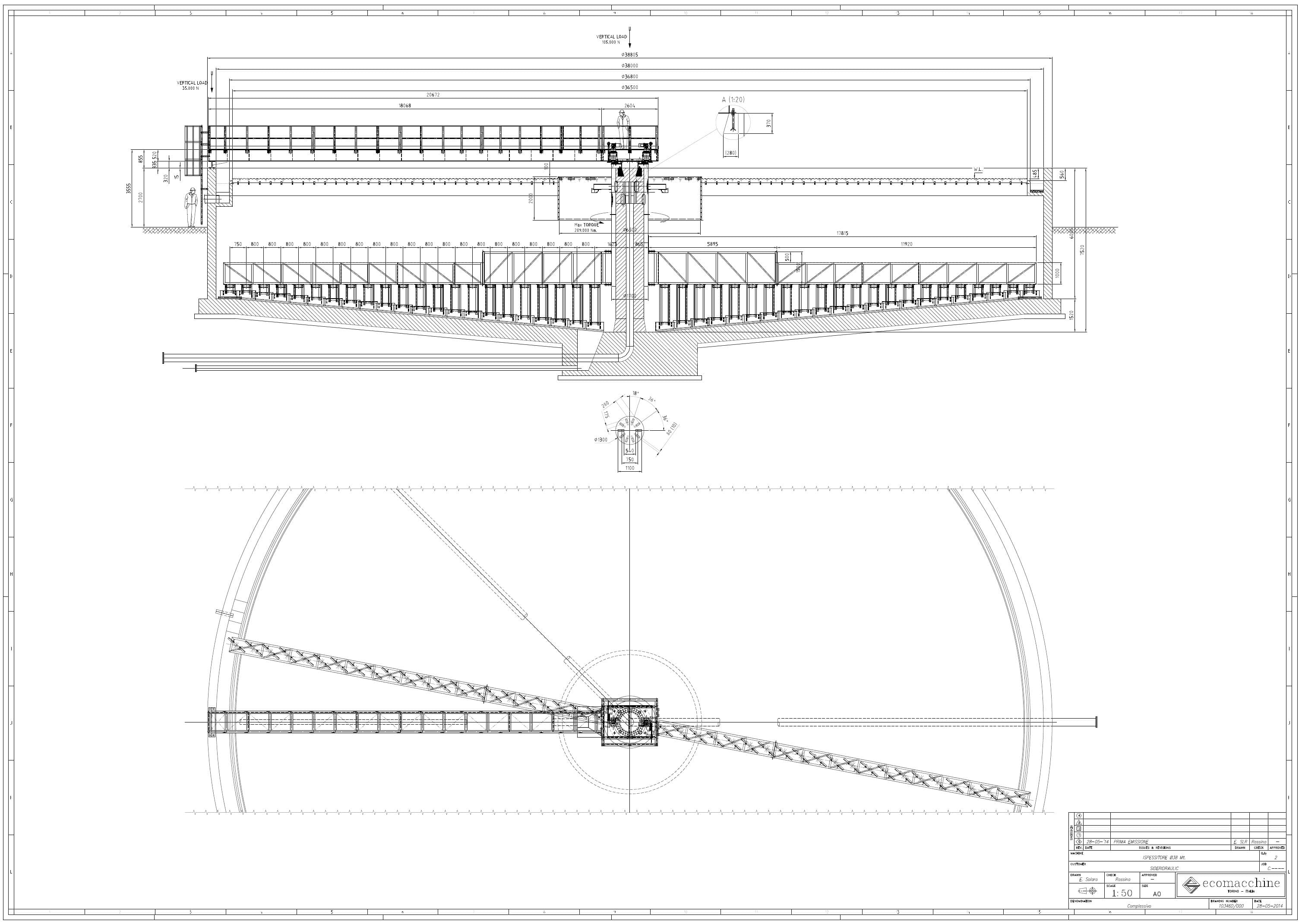
Ispessitore raschiante a trazione centrale
Lack of information...
EM16
Central drive scraping clarifier

EM16 – CENTRAL DRIVE SCRAPER BRIDGE FOR CIRCULAR TANK
| Application | Clarifying of primary and secondary waste water. |
| Characteristics | The equipment consists of a drive unit, a slow central shaft, two scraper arms, a diffusion drum. |
| Operation | The water to be treated flows into the diffusion drum where the kinetic energy is slowed down, the sedimentable solids settle on the tank bottom and are conveyed towards to central drain well by the bottom scrapers. |
| Materials | Hot dip galvanized carbon steel or Stainless steel. |
| Installation | In a concrete tank. |
| Tank diametre | From 2 to 30 m. |
| Optionals | Scum removal system |
PRINCIPLES OF SIZING
Hydraulic sizing (process) The sizing of the diffusion drum is based on the following parametres: • influent flow rate • piping diametre The water coming out of the diffusion drum to the sedimentation zone must have a very low kinetic energy in order to guarantee a good separation and settling of the solids. Moreover, the bottom scrapers must have a continuous and logarythmic profile in order to successfully convey the sludge into the central well in less than a complete rotation of the shaft, 270° (¾).
Mechanical Sizing The sizing of the bottom scraper is based on the type of sludge to be evacuated from the tank bottom. Normally the central shaft and the scrapers are designed to bear a stress of 20 Kg. per linear metre. The torque to transmit is calculated by: T [kgm] = r² x K r is the tank radius K is the load on the scrapers per linear metre (20 kg for biological clarifiers) For a reliability purpose, the drive unit shall be capable of transmitting a 1.8 higher torque than the design value.
Torque limiting device (dynamometric cell) The dynamometric cell measures the torque transmitted by the drive unit. This value is evident directly on the instrument and allows to evaluate the stresses on the central shaft during its rotation. The device is equipped with limit switches set at two different torque values, one for alarm and one for the machine shutdown.
Selection of the electric motor The electric motor size is selected so that, in case of shutdown, its static torque is lower than the one which can be borne by each downstream unit. For this reason the electric motor is usually very small. Exuberant motors may cause, in case of shutdown, serious damages to the structures if the torque limiting device fails to intervene or if it is not properly connected.
Example of calculation Tank diametre 10 m. K = 20 Scrapers peripheral speed 1,5 m/min Slow shaft rpm 0,047 Torque r² x K = 5² x 20 = 500 kgm so the drive unit shall be designed to transmit a 1.8 higher torque.
Electric Motor
To transmit a torque of 500 kgm at 0.047 rpm, 25 watt are necessary. If we hypothize a drive unit output of 60%, the electric motor shall have a power of 40 watt. Normally it is difficult to find electric motors which are smaller than 0,18 kw – 180 watt. If the selected motor has got a power of 180 watt, in case of shutdown it might give a 2.6 times higher power for a few seconds, i.e. 468 watt. The torque transmitted by the motor to the slow shaft, with a drive unit output of 60%, would be equal to 5700 kgm. In this case it should be evaluated whether to install a shear pin or a dynamometric cell to limit the torque.
EM18
Central drive, radial bridge, torsion trestle scraping clarifier
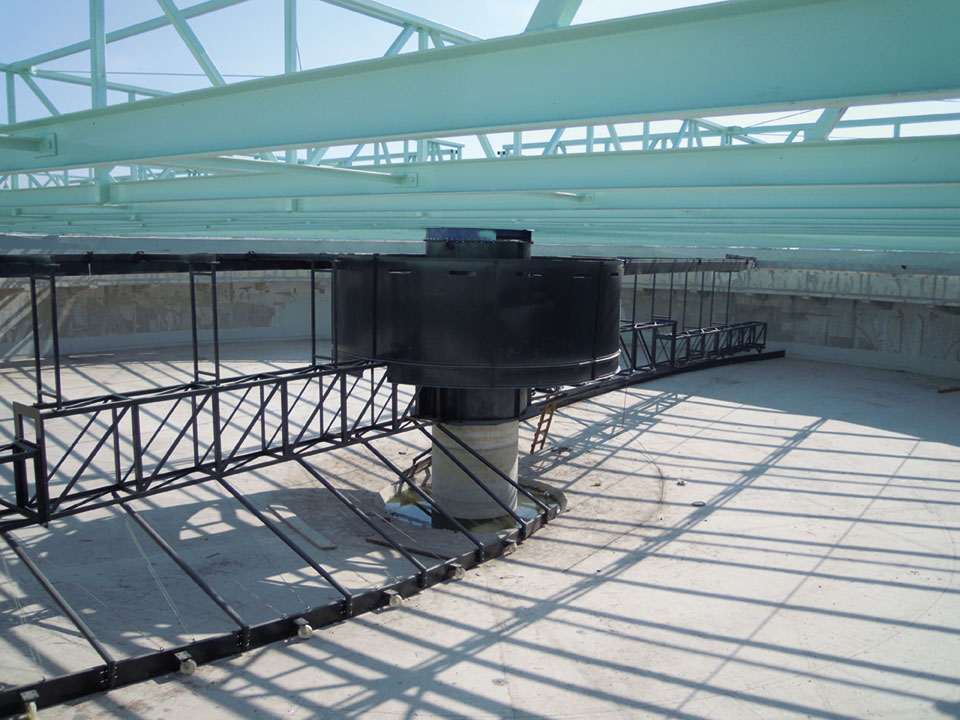
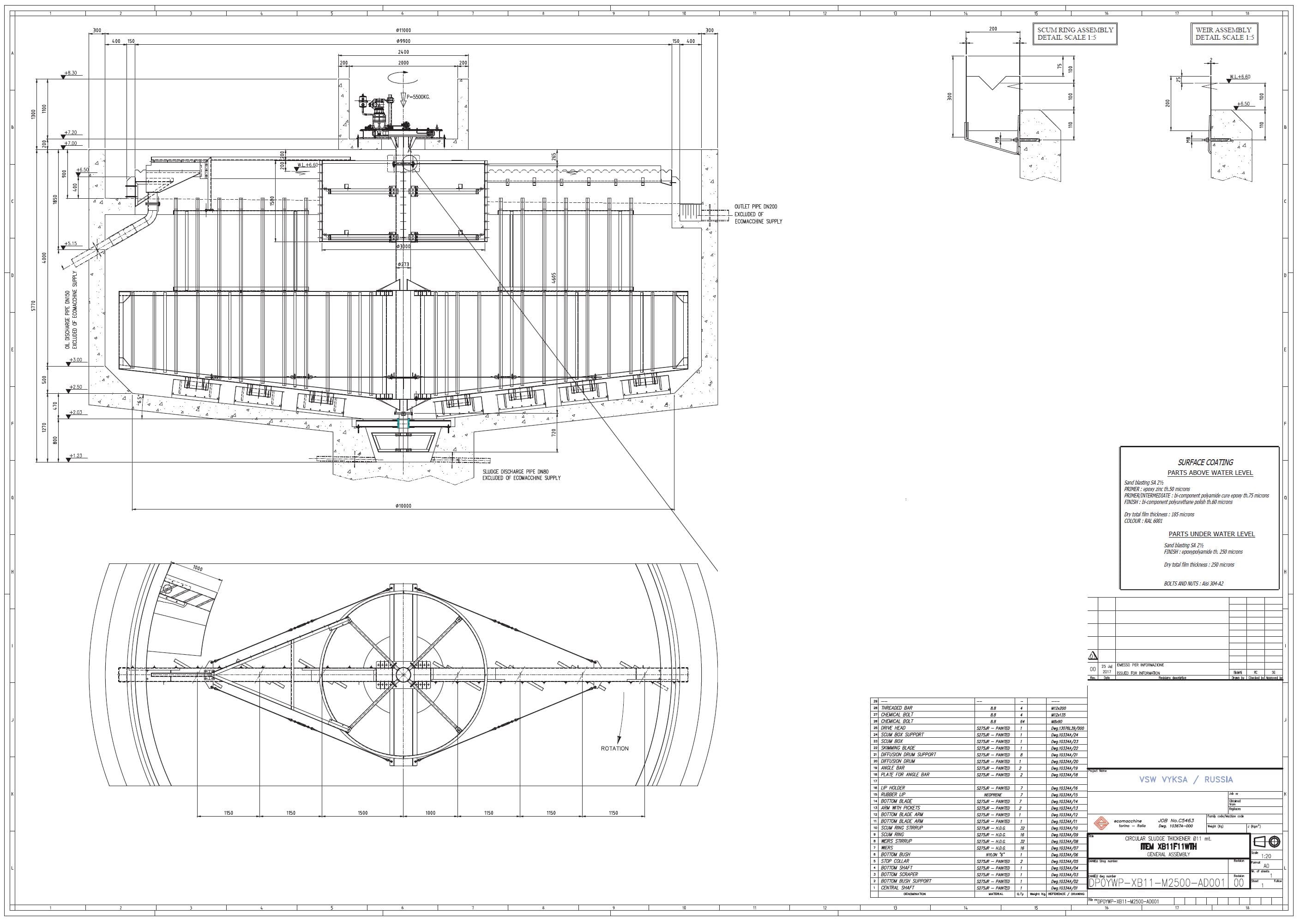
EM18 – SCRAPER BRIDGE WITH TORSION TRESTLE FOR CIRCULAR TANK
| Application | Clarifying of primary and secondary waste water |
| Characteristics | The equipment consists of a drive unit, a torsion trestle, two scraper arms, a diffusion drum. |
| Operation | The water to be treated flows into the diffusion drum where the kinetic energy is slowed down, the sedimentable solids settle on the tank bottom and are conveyed towards to central drain well by the bottom scrapers. |
| Materials | Hot dip galvanized carbon steel or Stainless steel |
| Installation | In a concrete tank |
| Tank diametre | From 2 to 50 m. |
| Optionals | Scum removal system |
PRINCIPLES OF SIZING
Hydraulic sizing (process) The sizing of the diffusion drum is based on the following parametres: • influent flow rate • piping diametre The water coming out of the diffusion drum to the sedimentation zone must have a very low kinetic energy in order to guarantee a good separation and settling of the solids. Moreover, the bottom scrapers must have a continuous and logarythmic profile in order to successfully convey the sludge into the central well in less than a complete rotation of the shaft, 270° (¾).
Mechanical Sizing The sizing of the bottom scraper is based on the type of sludge to be evacuated from the tank bottom. Normally the central shaft and the scrapers are designed to bear a stress of 20 Kg. per linear metre. The torque to transmit is calculated by T [kgm] = r² x K r è is the tank radius K is the load on the scrapers per linear metre (20 kg for biological clarifiers) For a reliability purpose, the drive unit shall be capable of transmitting a 1.8 higher torque than the design value.
Torque limiting device (dynamometric cell) The dynamometric cell measures the torque transmitted by the drive unit. This value is evident directly on the instrument and allows to evaluate the stresses on the trestle during the rotation. The device is equipped with limit switches set at two different torque values, one for alarm and one for the machine shutdown.
Selection of the electric motor The electric motor size is selected so that, in case of shutdown, its static torque is lower than the one which can be borne by each downstream unit. For this reason the electric motor is usually very small. Exuberant motors may cause, in case of shutdown, serious damages to the structures if the torque limiting device fails to intervene or if it is not properly connected.
Example of calculation
Tank diametre 20 m. K = 20 Scrapers peripheral speed 1,5 m/min Slow shaft rpm 0,023 Torque r² x K = 10² x 20 = 2000 kgm so the drive unit shall be designed to transmit a 1.8 higher torque.
Electric Motor
To transmit a torque of 2000 kgm at 0.023 rpm, 64 watt are necessary. If we hypothize a drive unit output of 60%, the electric motor shall have a power of 107 watt. Normally it is difficult to find electric motors which are smaller than 0,18 kw – 180 watt. If the selected motor has got a power of 180 watt, in case of shutdown it might give a 2.6 times higher power for a few seconds, i.e. 468 watt. The torque transmitted by the motor to the torsion trestle, with a drive unit output of 60%, would be equal to 5700 kgm. In this case it should be evaluated whether to install a shear pin or a dynamometric cell to limit the torque.
-
EM18 ATLATEC-MESSICO-C04935-1

-
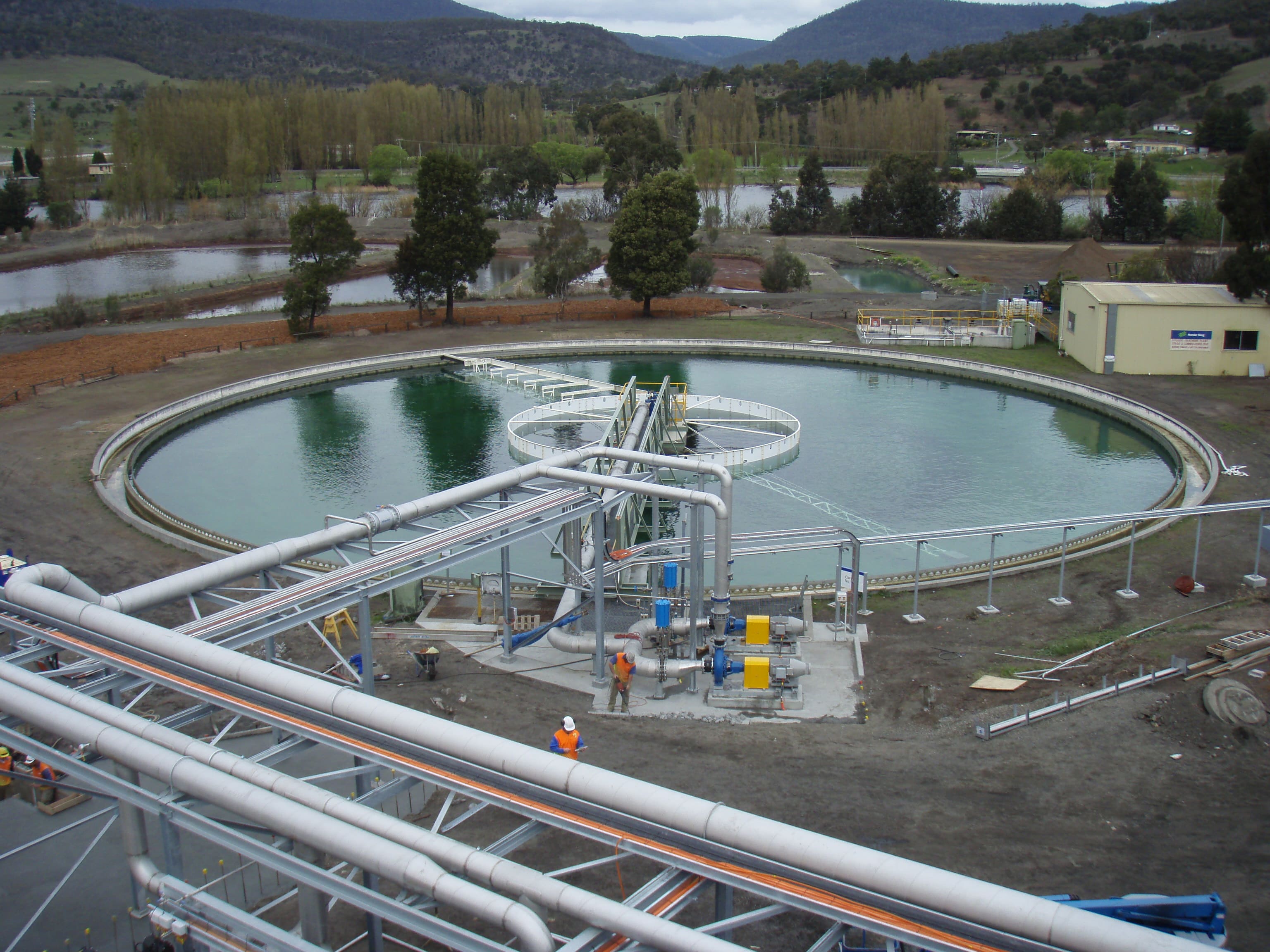
EM18 D50m-NorskeSkog2 Tasmania
-
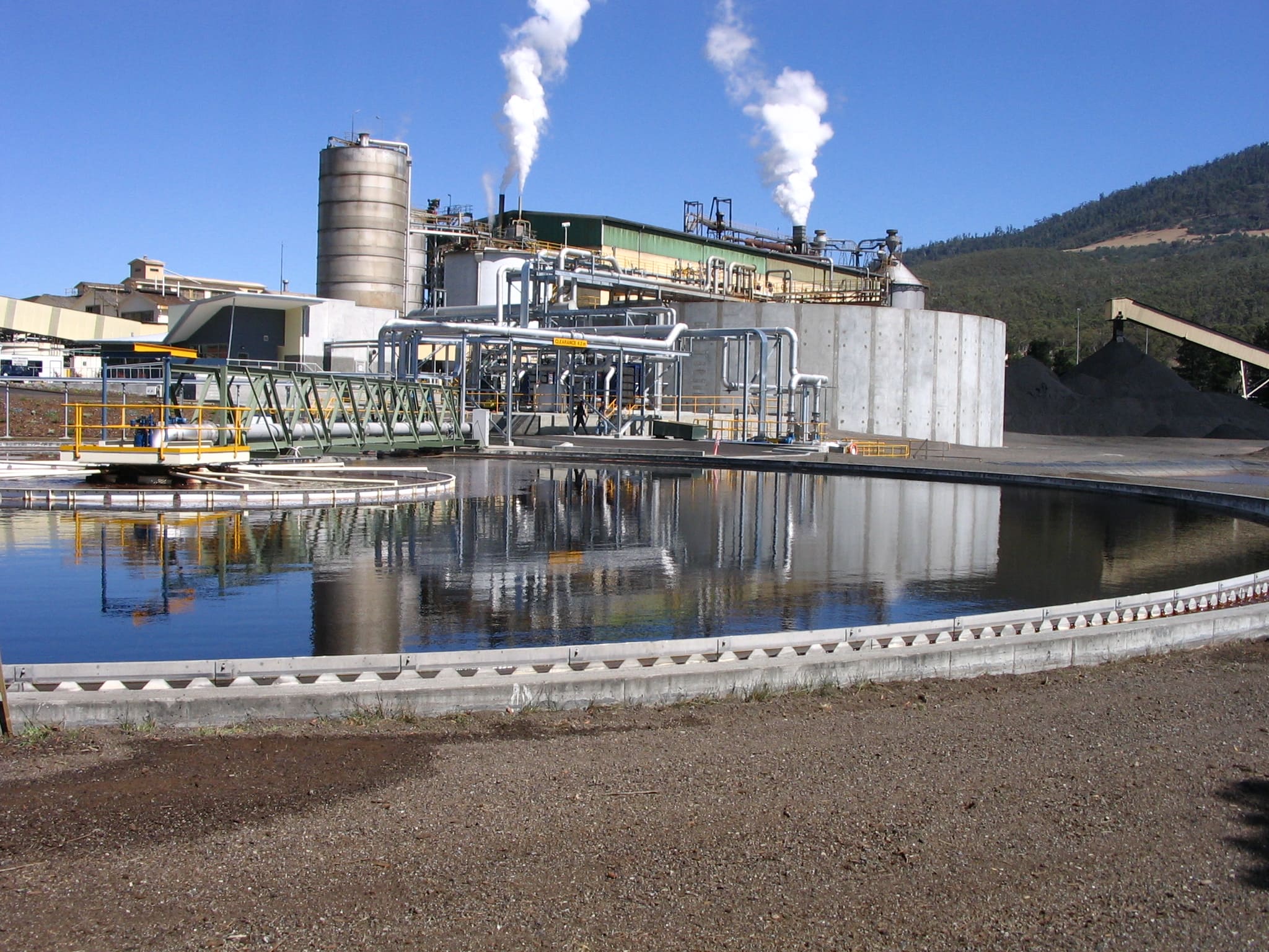
EM18 D50m-NorskeSkog Tasmania
EM30
Central drive, radial bridge, torsion trestle suction type clarifier
EM30 – CENTRAL DRIVE – SUCTION TYPE SCRAPER BRIDGE WITH TORSION TRESTLE, FOR CIRCULAR TANK
| Application | Clarifying of secondary waste water |
| Characteristics | The equipment consists of a rotating bridge and a torsion trestle with suction pipes all over the tank diametre. |
| Operation | The water to be treated flows into the diffusion drum where the kinetic energy is slowed down, the sedimentable solids settle on the tank bottom and are sucked by the suction pipes equipped with regulating telescopic valves. |
| Materials | Hot dip galvanized carbon steel or Stainless steel |
| Installation | In a concrete tank |
| Tank diametre | From 8 to 60 m. |
| Optionals | Scum removal system |
PRINCIPLES OF SIZING
Sludge suction unit sizing. For the project of the sludge suction unit we have to make sure that the sludge is quickly removed from the tank bottom because if it tends to settle or get too thick for staying in the tank for a too long time, it may happen that: • a part of the recycled sludge returns to the oxidation tank when it is no more fresh and this will affect the treatment efficiency • a shortage of dissolved oxygen may cause a leakage of sludge in the effluent
Mechanical Sizing Same principles as described for the Central drive scraper bridge mod. EM16.
OPERATION DESCRIPTION
The bottom of the suction scraper bridge tank is flat and the suction pipes, sized according to sludge recycle flow rate, are placed at a distance which does not exceed 3 m. The sludge is conveyed towards the suction pipe by V-shaped scrapers which make the flowing of the sludge towards the piping much easier. Each suction pipe is equipped with a telescopic valve to regulate the flow into the hopper. The quality and quantity of sludge sucked by each pipe can be checked from the bridge. The sludge flows into the hopper according to the principle of the communicating vessels. The sludge flow rate depends on the difference of level between the water surface and the sludge level in the hopper. The sludge sucked by all of the suction pipes is conveyed out of the tank by means of a self-regulating siphon. The triggering of the siphon can be made during the commissioning phase by means of a pump or ejector.
TECHNICAL AND DIMENSIONAL DATA NECESSARY TO MAKE A TECHNICAL PROPOSAL AND QUOTATION
| 1. | Flow rate to the sedimentation tank (total) | : m3/h |
| 2. | Flow rate coming from the sedimentation tank (at the overflow weir) | : m3/h |
| 3. | Flow rate of sludge coming from the sedimentation tank | : m3/h |
| 4. | Tank diameter | : m. |
| 5. | Diameter of the feed pipe | : mm. |
| 6. | Sludge level in the drain well | : +m. |
| 7. | Water level in the sedimentation tank | : +m. |
Accessories
Oil and grease collecting system with scraping blade
Oil and grease collecting system with submersible pump
Weirs and scum blades automatic cleaning system with motorized brush
Telescopic valve
Ice protection on running path
Wheel slipping alarm
OUTLINES OF THE SEDIMENTATION PROCESS
A good efficiency of the sedimentation process gives as a result a considerable reduction of BOD, COD, heavy metals, azote, phosphorus, etc. in the treated water. As the suspended substances in the waste water become larger, their sedimentation becomes easier.Stokes’ law emphasizes the importance of the floc size for the speed of sedimentation.
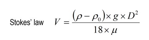
V = speed of sedimentation in m/s ρ = density of solids in kg/m³ ρ0 = densità dell’acqua kg/m³ g = 9,81 m/s2 μ = viscosity of water in in Pa x s (at 15° C the viscosity of water is 1,06 x 10⁻³ Pa x s) D = diametre of the particle in m.
A good way to obtain large flocs in the clarifier feeding is the installation of baffles using the kinetic energy of water to agglomerate the flocs to each other
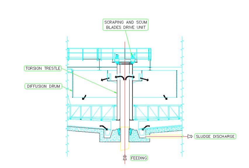
In the secondary clarifiers, the type of scraping blades and the sizing of the central drain well are very important.
Actually, given the enormous volume of “sludge” compared to the feed flow rate (50%), we can hypothize that the sludge characteristics are just a little different from the ones of the clarified water (under static conditions the clarified water and the sludge stratify with a horizontal separation surface) and that, consequently, due to the slight bottom slope (∼ 4%), it flows naturally towards the central well. However, we should not forget that the particles which touch the bottom, and the ones which stratify, adhere and loose the properties of “fluid”: so they must be actively moved and “pushed” towards the drain well before the layer becomes too thick and, above all, before the anoxic condition causes a strong de-nitrification with the production of floating plates. Therefore all of the sedimented sludge particles conveyed by the bottom scrapers to the central well from the tank periphery, must reach it quickly. This is achieved by giving a continuous profile with logarythmic shape to the blade; the relevant equation in polar coordinates is:
r=r0·emα
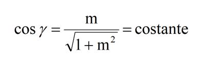
where r and α are the polar coordinates having the tank centre as a pole and ro is the radius of the drain well. Under these conditions, the scraper moves the sludge, makes it more “fluid” (by eliminating the adhesion) and conveys it by a perpendicular force to its surface (Pascal); this force has a radial centripetal component, not null and constant. The angle γ is determined by:
 EM10A C5463-Vyksa RUS
EM10C C5224-Rimini ITA
EM10D C5281-Lagos NIG
EM17 AlKhumrah
EM10A C5463-Vyksa RUS
EM10C C5224-Rimini ITA
EM10D C5281-Lagos NIG
EM17 AlKhumrah
 EM17 BeniMessous
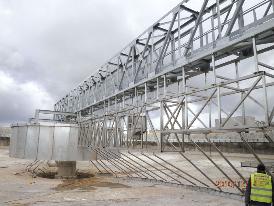 EM17A1 58-mTunisia-1
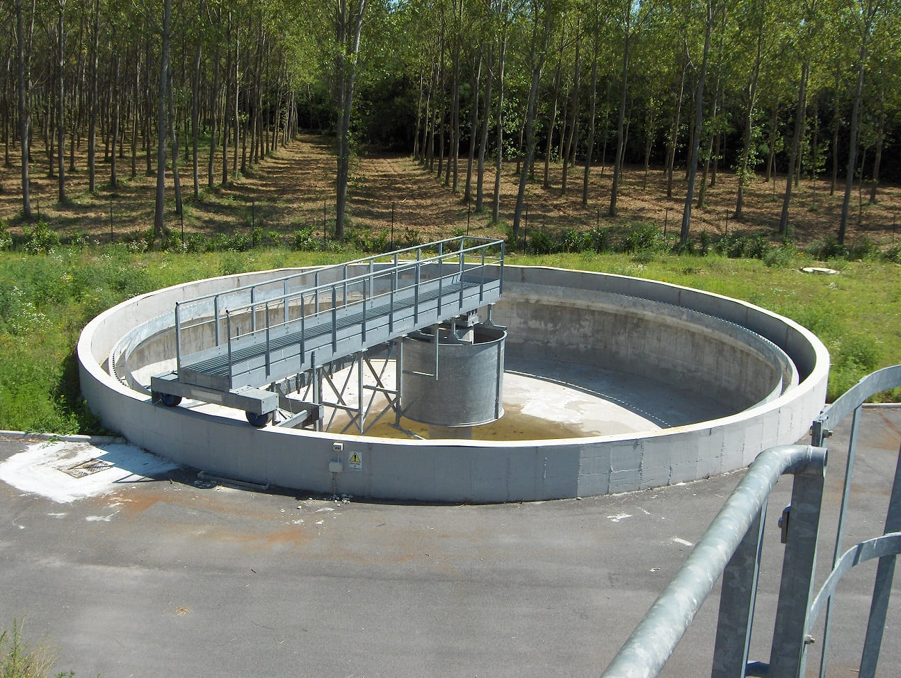 EM17A1 Italia
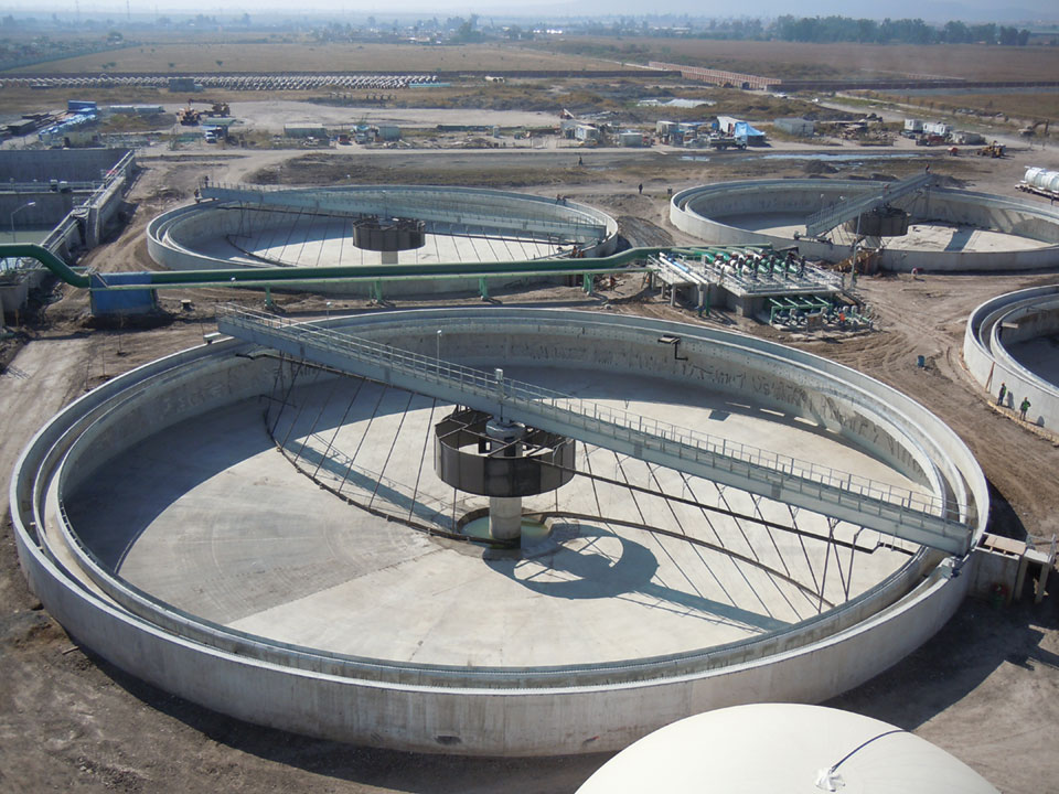 EM17C ATLATEC-MESSICO-C04935-2
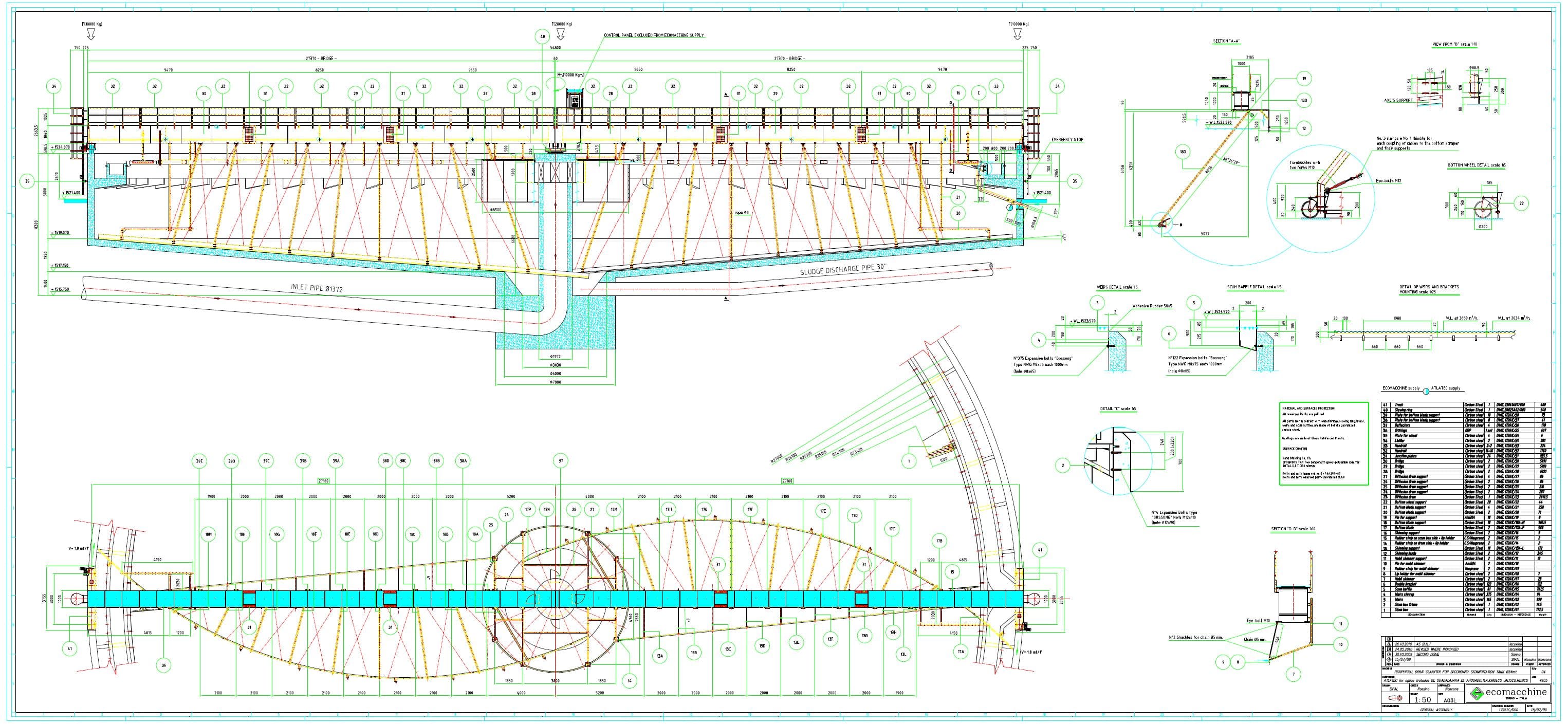 EM17C C4935-Guadalajara MEX
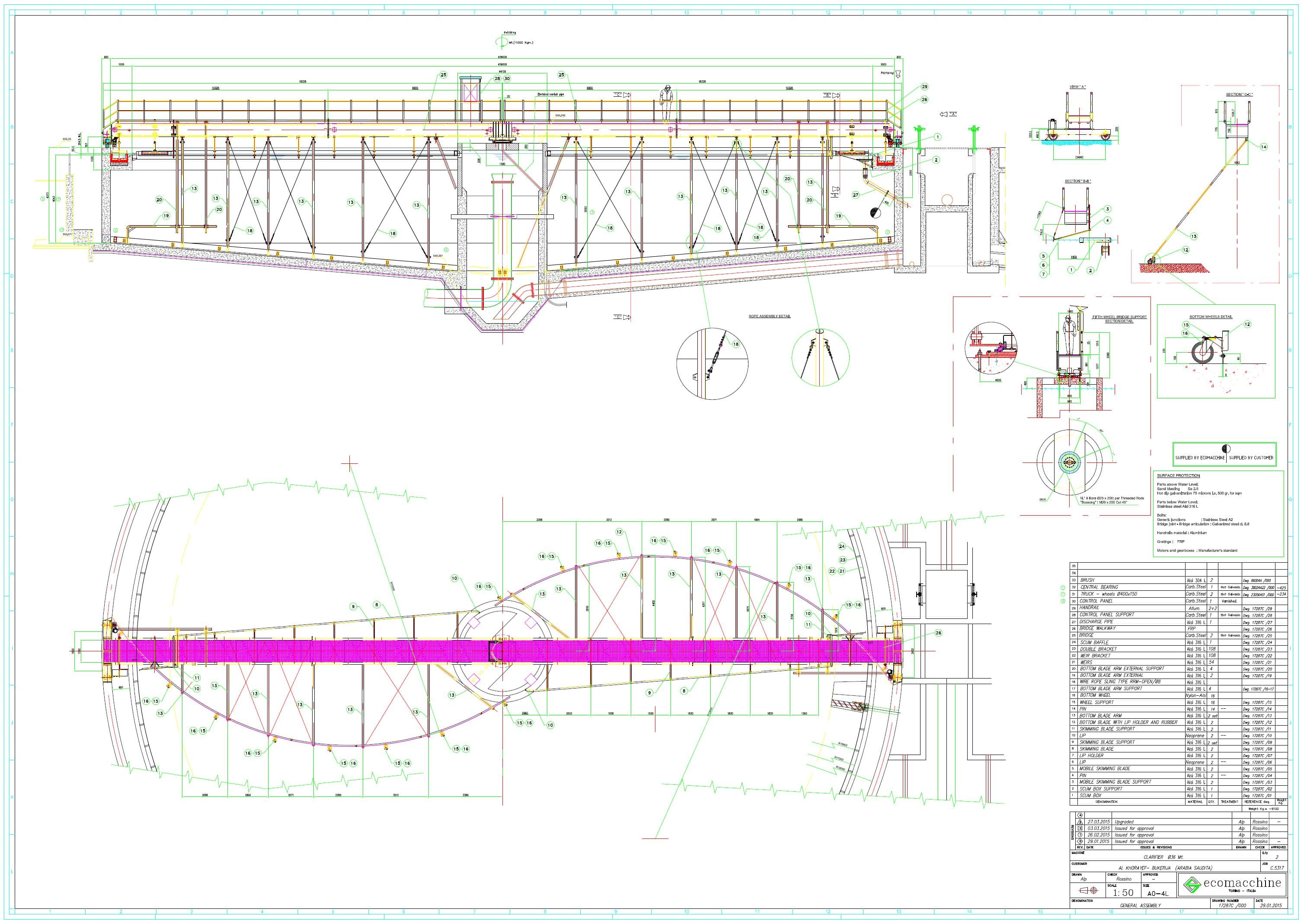 EM17C C5317-Al-Khorayef KSA
EM18 ATLATEC-MESSICO-C04935-1
EM17C C5317-Al-Khorayef KSA
EM18 ATLATEC-MESSICO-C04935-1
 EM18 D50m-NorskeSkog2 Tasmania
 EM18 D50m-NorskeSkog Tasmania
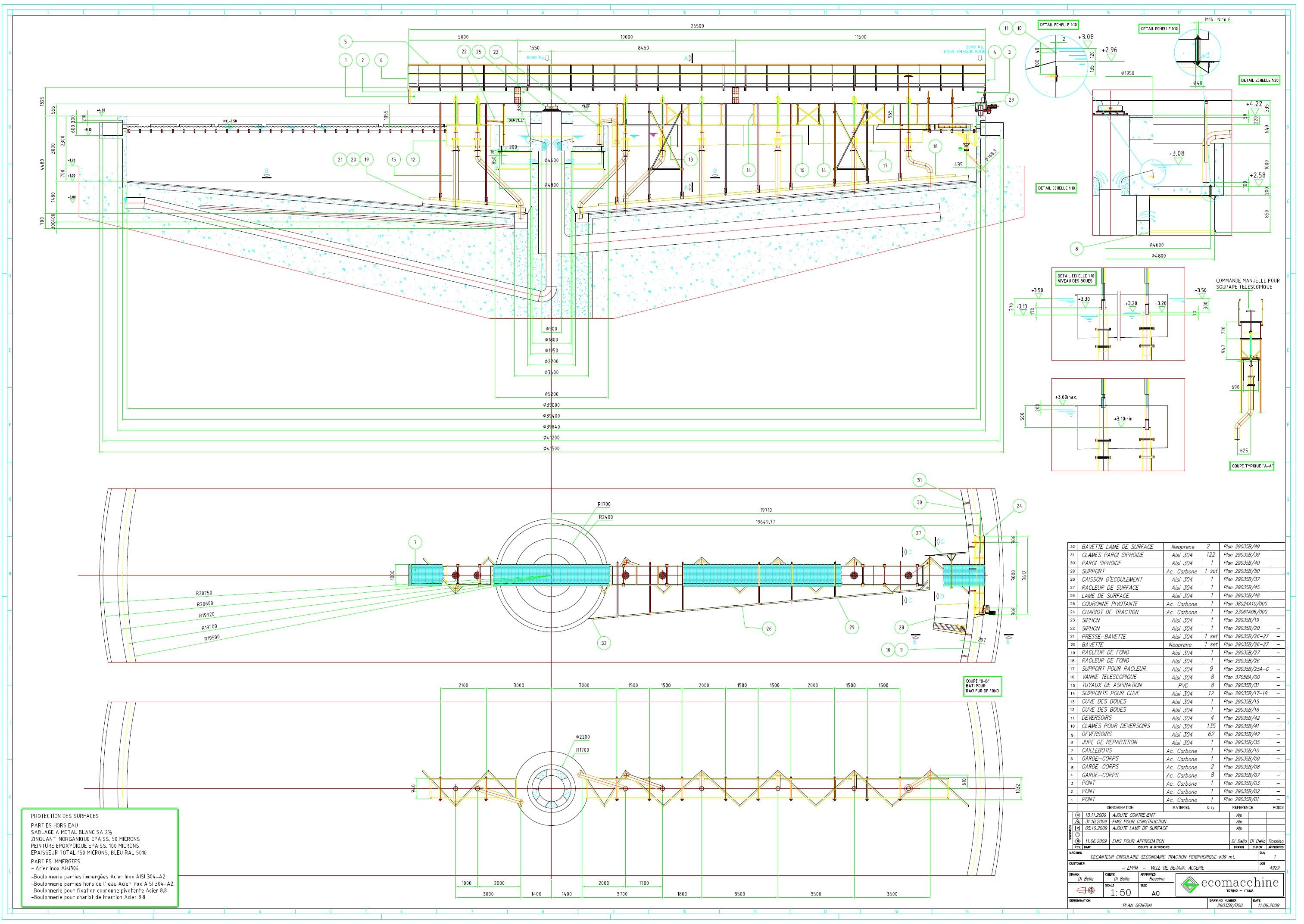 EM29B C4929-Bejaja Algerie
EM29C C04678
EM29B C4929-Bejaja Algerie
EM29C C04678