Language switcher


Grit & grease removal equipment
It is a process used to remove sand and inert materials that can cause abrasion and clogging problems in treatment plants.
Application
Municipal water and wastewater grit removal
Industrial water and wastewater grit removal
Scraping or suction equipment for rectangular tanks
Models
EM54
Hydraulic or mechanical scraping blades lifting scraping bridge
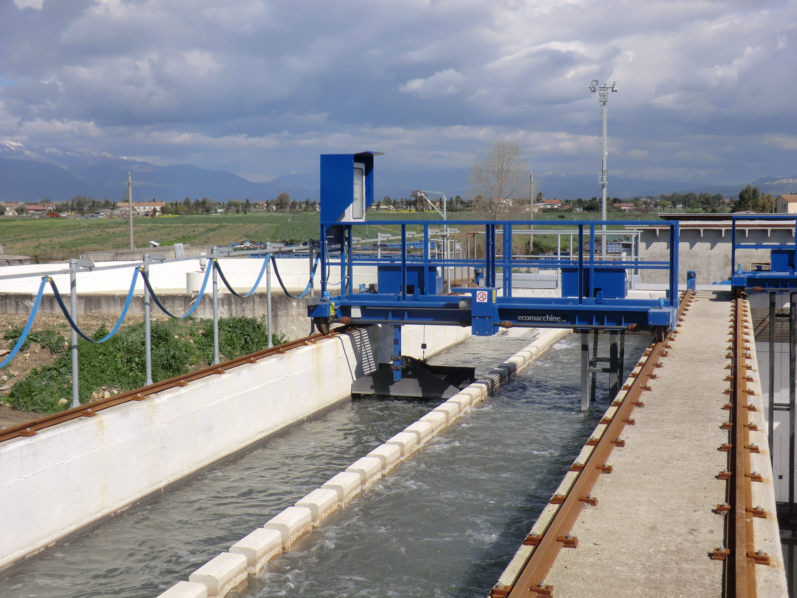
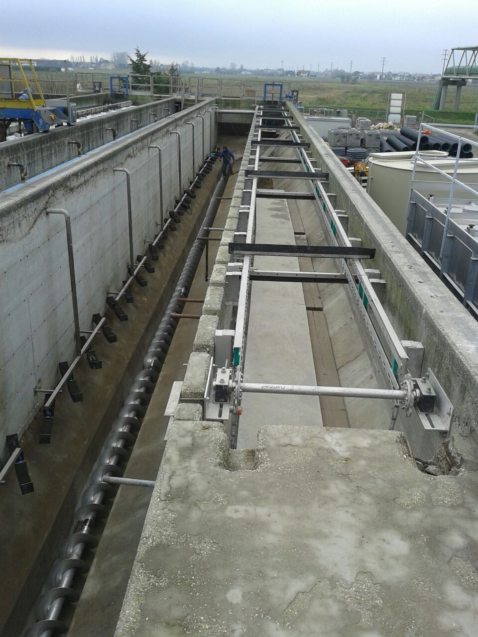
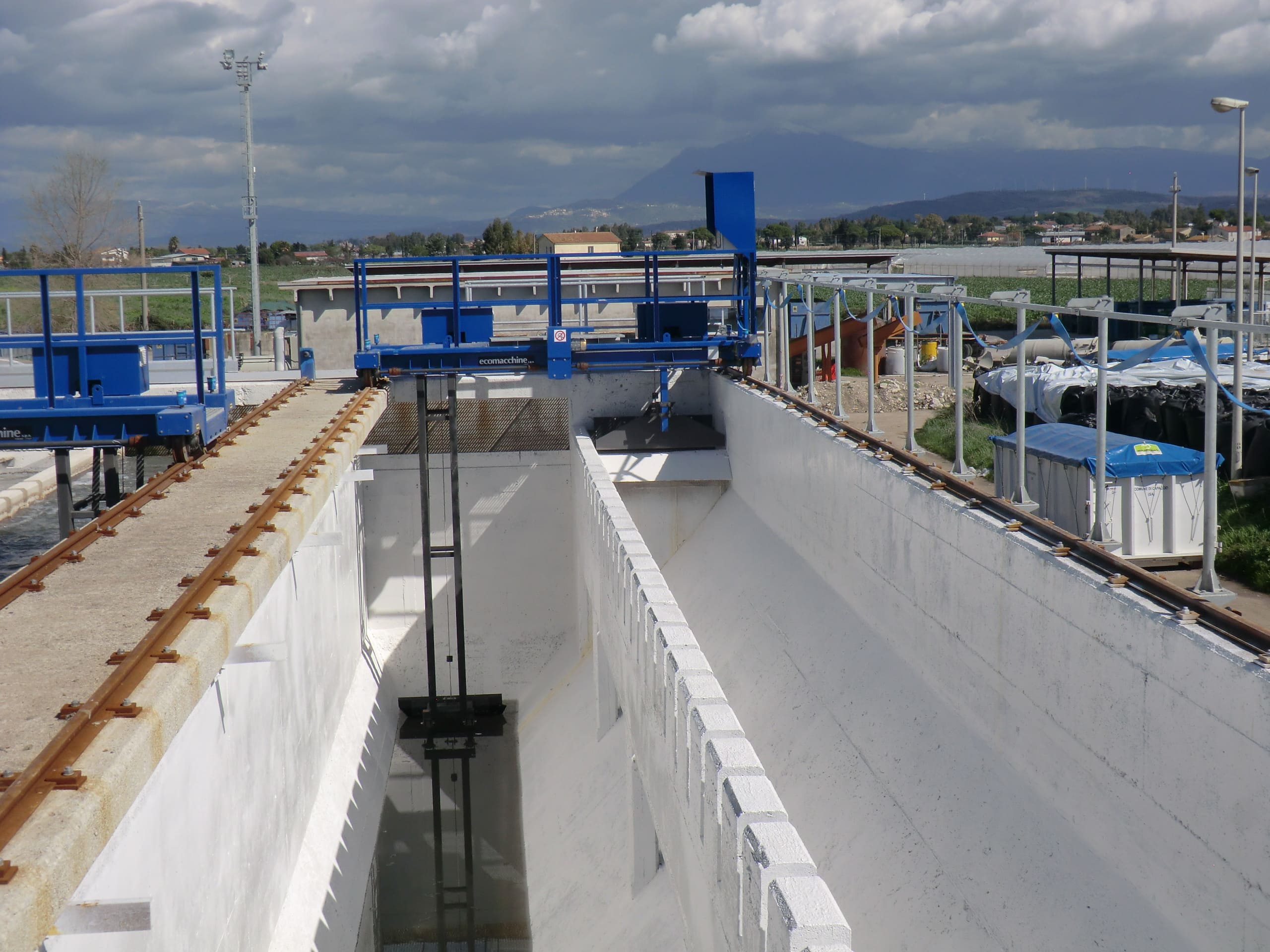
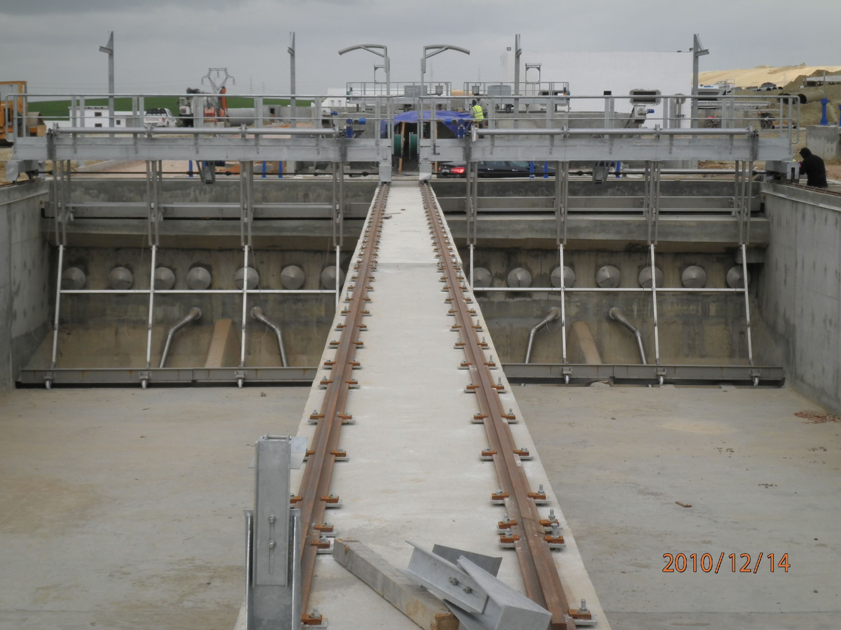
EM54 – GRIT AND OIL REMOVAL SCRAPER BRIDGE, AERATED TYPE
| Application | Grit and oil removal from municipal and industrial waste water. |
| Characteristics | Longitudinal flow channel, with tapered section (downwards). The channel is divided into two zones: the grit removal zone (normally aerated) the oil removal zone. The two zones are separated by a longitudinal baffle. |
| Operation | The waste water goes through the grit removal system longitudinally; the grit which sediments on the bottom is scraped and conveyed into a hopper and then lifted by air-lifts or submersible pumps. The floating substances in the oil removal zone are conveyed to the hopper by a surface scraper. |
| Materials | Compact equipment in hot dip galvanized carbon steel or stainless steel. |
| Installation | In a concrete channel. |
| Separation | Grit particles larger than 200 microns. |
| Optional | Separation between grit removal-oil removal zones. Power supply by cable winding reel. Air blowing system. |
OPERATION DESCRIPTION
The water speed in the grit removal channel is lower than 0.3 m/sec., therefore the grit having a larger size than 200 microns settles on the bottom. The air distributed by the diffusers fluidifies the grit before it sediments and removes the organic substances which deposit on it. These organic substances and the other substances in the water, thanks to the air effect, float and flow together to the oil removal zone which is on the channel side and is not aerated, then they are taken away by a surface scraper. The grit settled on the bottom is conveyed to the hopper by the bottom scraper. The recommended air delivery is of 10-15 Nm3/h per metre of length of the grit removal channel.
MECHANICAL SOLUTIONS FOR THE SCRAPER BRIDGES
- scraper bridge with concrete runways, equipped with tyred wheels and contrast wheels
- scraper bridge with rails
TECHNICAL DATA
| 1.1 | Max. flow rate in the channel | :m³/h | (*) |
| 1.2 | Width of the grit removal zone | :mm. | (*) |
| 1.3 | Width of the oil removal zone | :mm. | (*) |
| 1.4 | Channel length | :mm. | (*) |
| 1.5 | Aeration zone air flow rate | :m³/h | |
| (*) To be advised when asking for a quotation | |||
EM55
Suction system with air-lift or vertical or submersible pump bridge
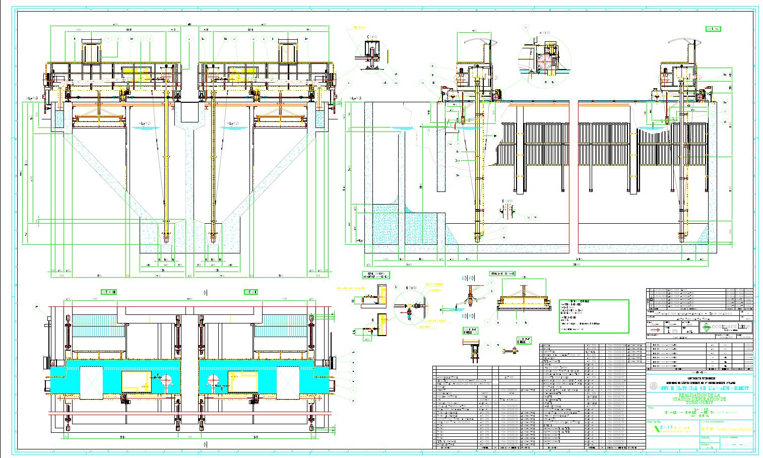
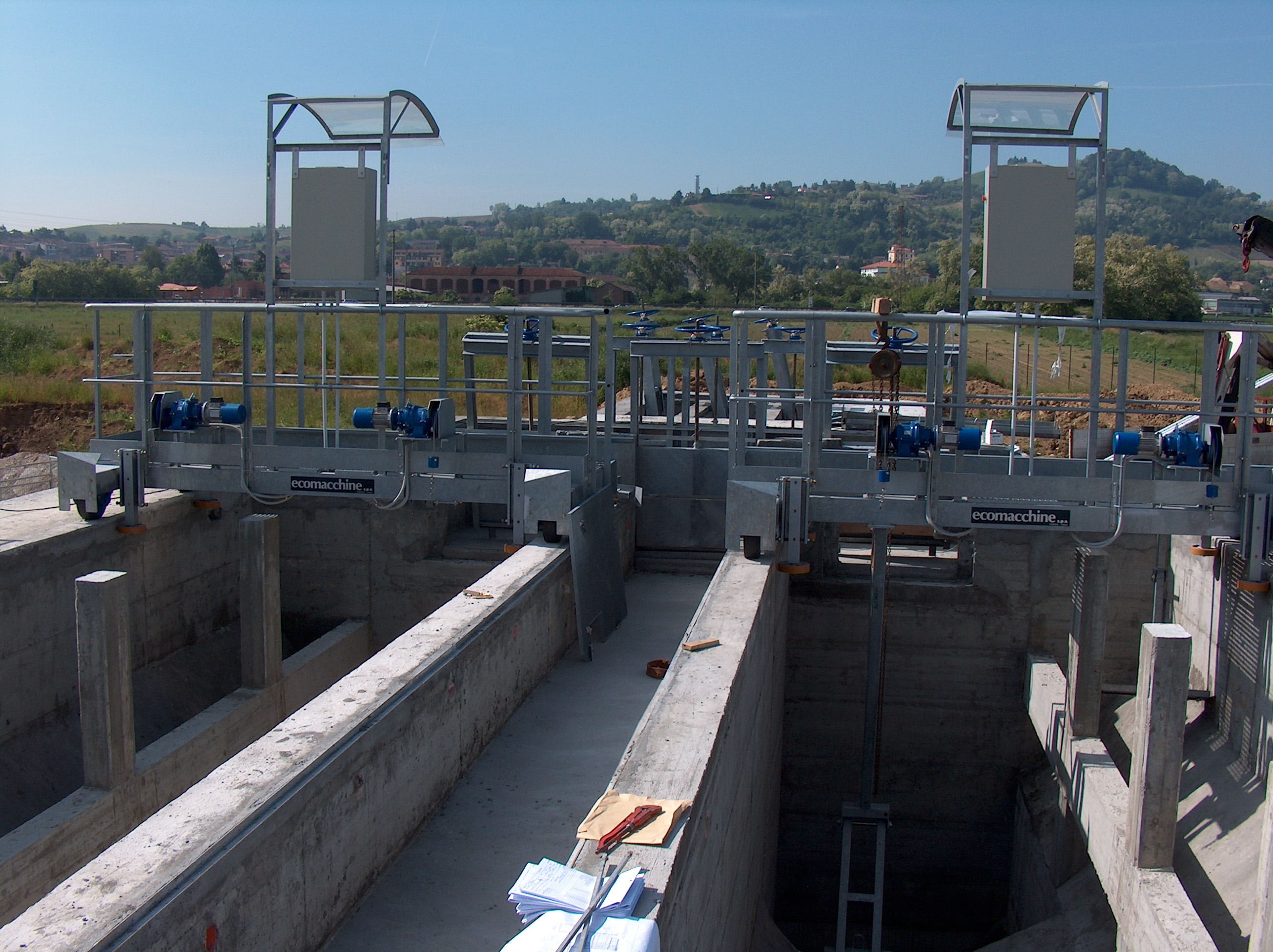
EM55 – GRIT AND OIL REMOVAL SCRAPER BRIDGE, SUCTION TYPEE
| Application | Grit and oil removal from municipal and industrial waste water. |
| Characteristics | Longitudinal flow channel, with tapered section (downwards). The channel is divided into two zones: the grit removal zone (normally aerated) the oil removal zone. The two zones are separated by a longitudinal baffle. |
| Operation | The waste water goes through the grit removal system longitudinally; the grit which sediments on the bottom is lifted and conveyed to a lateral channel by air-lifts or submersible pumps. The floating substances in the oil removal zone are conveyed to the hopper by a surface scraper. |
| Materials | Compact equipment in hot dip galvanized carbon steel or stainless steel. |
| Installation | In a concrete channel. |
| Separation | Grit particles larger than 200 microns. |
| Grit lifting systems | Air-lift Submersible pump Vertical pump |
| Optional | Separation between grit removal-oil removal zones. Power supply by cable winding reel. Air blowing system. |
OPERATION DESCRIPTION
The water speed in the grit removal channel is lower than 0.3 m/sec., therefore the grit having a larger size than 200 microns settles on the bottom. The air distributed by the diffusers fluidifies the grit before it sediments and removes the organic substances which deposit on it. These organic substances and the other substances in the water, thanks to the air effect, float and flow together to the oil removal zone which is on the channel side and is not aerated, then they are taken away by a surface scraper. The grit settled on the bottom is lifted by a submersible pump or air-lift and conveyed to the lateral channel. The recommended air delivery is of 10-15 Nm3/h per metre of length of the grit removal channel.
MECHANICAL SOLUTIONS FOR THE SCRAPER BRIDGES
- scraper bridge with concrete runways, equipped with tyred wheels and contrast wheels
- scraper bridge with rails
TECHNICAL DATA
| 1.1 | Max. flow rate in the channel | :m³/h | (*) |
| 1.2 | Width of the grit removal zone | :mm. | (*) |
| 1.3 | Width of the oil removal zone | :mm. | (*) |
| 1.4 | Channel length | :mm. | (*) |
| 1.5 | Aeration zone air flow rate | :m³/h | |
| (*) to be advised when asking for a quotation | |||
Scraping equipment for covered tanks
Models
EM52
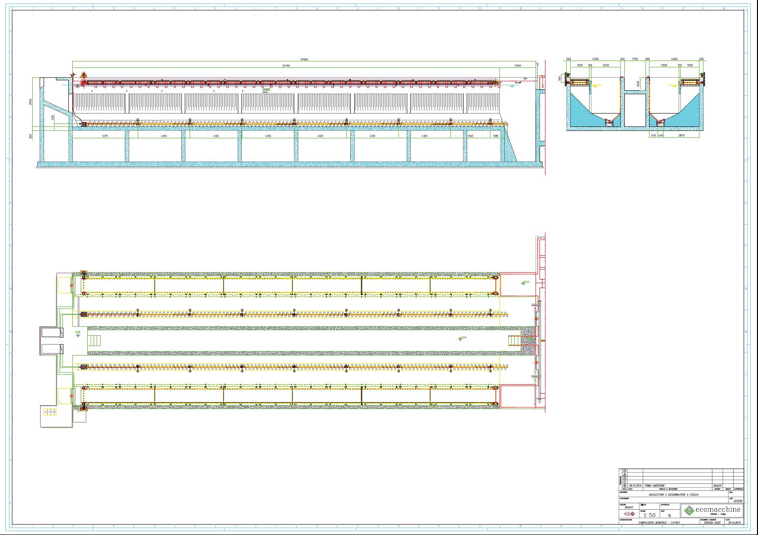
Grease removal dredging chain and grit removal bottom screw
Lack of information...
Suction equipment for circular and square tanks
Models
EM40A
Grit and grease removal system vortex type

EM40A – VORTEX GRIT REMOVAL SYSTEM
| Application | Grit and oil removal from municipal and industrial waste water. |
| Characteristics | The system is made up of a turbine and an air-lift. |
| Operation | The water to be treated goes through the grit removal system with a tangential flow; the grit which sediments on the bottom is lifted by an air-lift. |
| Materials | Compact equipment in hot dip galvanized carbon steel or stainless steel. |
| Installation | In a concrete channel. |
| Tank diameter | From 1000 to 5000 mm. |
| Separation | Grit particles larger than 200 microns. |
| Advantages | The grit moved by the turbine is partially separated from the organic substances. |
| Disadvantages | Limited capacity of treatment. It does not include any oil removal system. |
| Optional | Blower |
OPERATION DESCRIPTION
The water flows into the grit removal tank in a tangential way and the blades keep the liquid in motion at any level of flow rate. The tangential flow and the blades rotation make the grit particles sediment on the bottom. The grit is lifted by an air-lift and is conveyed to a mechanical separator or to a simple draining and filtering bed. The grit removed is clean enough thanks to the separation of the organic substances due to the effect of the rotary blades.
Sometimes, to avoid the arising of decomposition phenomena due to the inevitable presence of organic material, a certain number of washings by water or air are necessary before extracting the grit.
This type of grit removal system does not separate any oily substances.
TECHNICAL DATA
| 1.1 | Waste water delivery to the grit removal system | :m³/h | (*) |
| 1.2 | Useful diameter | :mm. | |
| 1.3 | Water and sand flow rate in the air-lift | :m³/h | (*) |
| 1.4 | Air-lift size | :DN. | |
| 1.5 | Rotation speed | :rpm | 30 |
| (*) to be advised when asking for a quotation | |||
EM40B
Central drive grease removal and air-lift pump grit removal
EM40B – VORTEX GRIT AND OIL REMOVAL SYSTEM
| Application | Grit and oil removal from municipal and industrial waste water. |
| Characteristics | The system is made up of a separation cylinder, air diffusers and an air-lift. |
| Operation | The water to be treated goes through the grit removal system with a tangential flow; the grit which sediments on the bottom is lifted by an air-lift. The oily substances which float due to the effect of the air blowing are evacuated by means of a valve, normally with a manual control. |
| Materials | Compact equipment in hot dip galvanized carbon steel or stainless steel. |
| Installation | In a concrete tank. |
| Tank diameter | From 1000 to 5000 mm. |
| Separation | Grit particles larger than 200 microns. |
| Advantages | It is equipped with oil removal system. |
| Disadvantages | Limited capacity of treatment |
OPERATION DESCRIPTION
The water flows into the grit removal tank in a tangential way. The tangential flow helps the grit particles sedimentation on the tank bottom. Normally the suspension remains in the tank more than 30 seconds. The flotation of the organic substances is due to the air blowing. The grit is lifted by an air-lift and is conveyed to a mechanical separator or to a simple draining and filtering bed. The oils flow together outside the separation ring and are regularly removed by means of a manual blade or gate valve. The grit removed is clean enough thanks to the separation of the organic substances due to the effect of the air blowing.
To avoid the arising of decomposition phenomena due to the inevitable presence of organic material, a certain number of washings by water are necessary before extracting the grit.
TECHNICAL DATA
| 1.1 | Waste water delivery to the grit removal system | :m³/h | (*) |
| 1.2 | Useful diameter | :mm. | |
| 1.3 | Water and sand flow rate in the air-lift | :m³/h | (*) |
| 1.4 | Air-lift size | :DN. | |
| 1.5 | Air flow rate | :Nm³/h | |
| (*) to be advised when asking for a quotation | |||
EM40D
Centrally driven skimmer and suction desander with airlift
Lack of information...
EM40E
De-oiling gritter with skimmer and centrally driven scraper blades
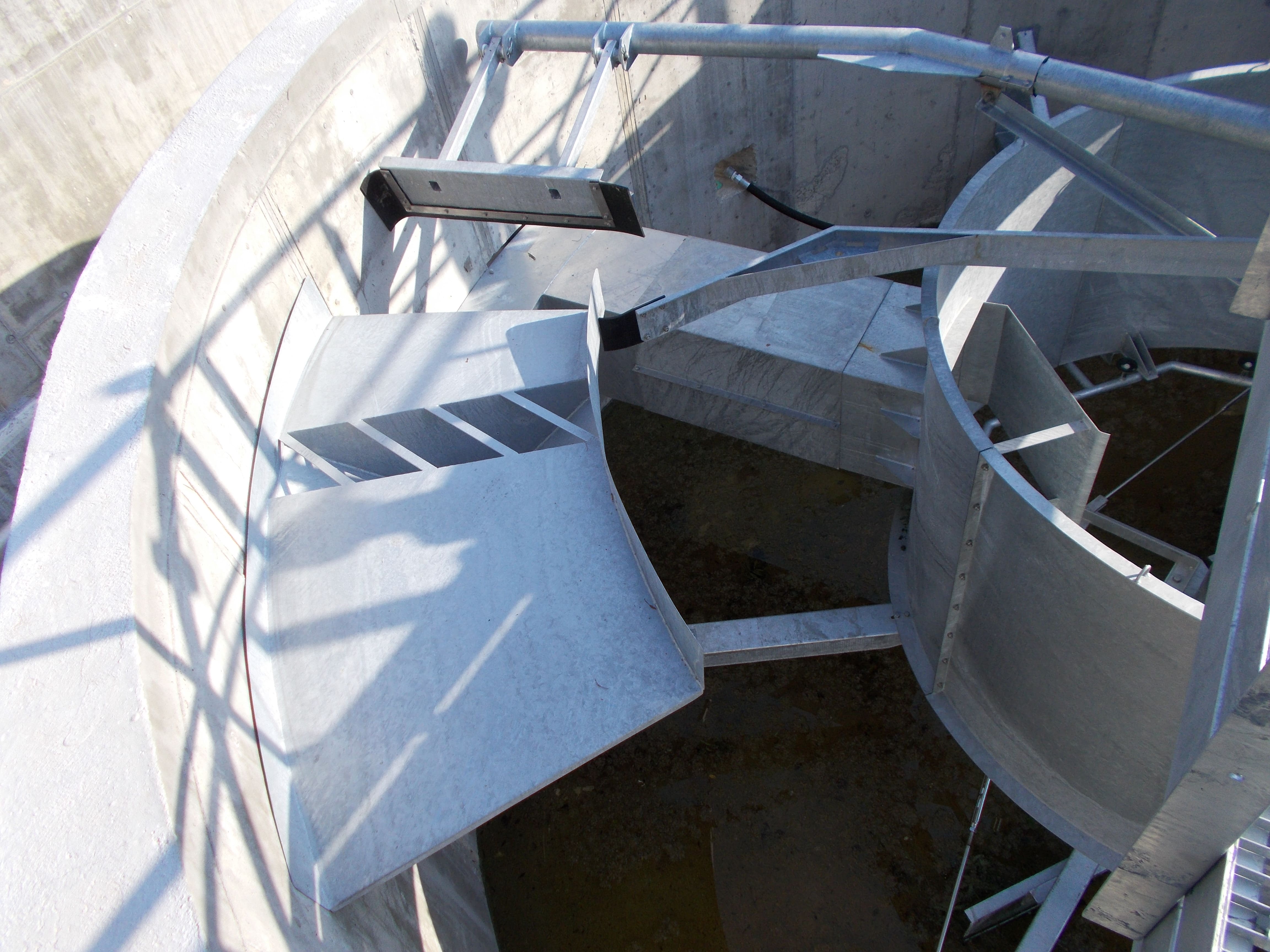
Lack of information...
EM42
Central drive grit removal detritor type for square basins
EM42 – DETRITOR TYPE GRIT REMOVAL SYSTEM
| Application | Grit removal from municipal and industrial waste water. |
| Characteristics | The system is equipped with baffles and grit scrapers. |
| Operation | The water to be treated goes through the grit removal system with a laminar flow; the grit which sediments on the bottom is conveyed to the sides and evacuated by an air-lift. |
| Materials | Compact equipment in hot dip galvanized carbon steel or stainless steel. |
| Installation | In a concrete tank. |
| Tank diameter | From 2000 to 16000 mm. |
| Separation | Grit particles larger than 200 microns. |
| Optional | Air-lift for grit evacuation |
OPERATION DESCRIPTION
The water flows into the grit removal tank from the side. The water flow must have a laminar motion. The baffles placed at the entry are installed in such a way to distribute the water homogeneously, all over the tank width.
The grit which sediments on the bottom is scraped and conveyed to the periphery of the tank where it is lifted and evacuated by an air-lift. The average water level in the tank is 700-1000 mm.
TECHNICAL DATA
| 1.1 | Waste water delivery to the grit removal system | :m³/h | (*) |
| 1.2 | Width x length | :mm. | |
| 1.3 | Water and sand flow rate in the air-lift | :m³/h | (*) |
| 1.4 | Air-lift size | :DN. | |
| 1.5 | Rotation speed of the scrapers | :rpm | |
| (*) to be advised when asking for a quotation | |||
Accessories
Models
EM39
Screw type grit classifier
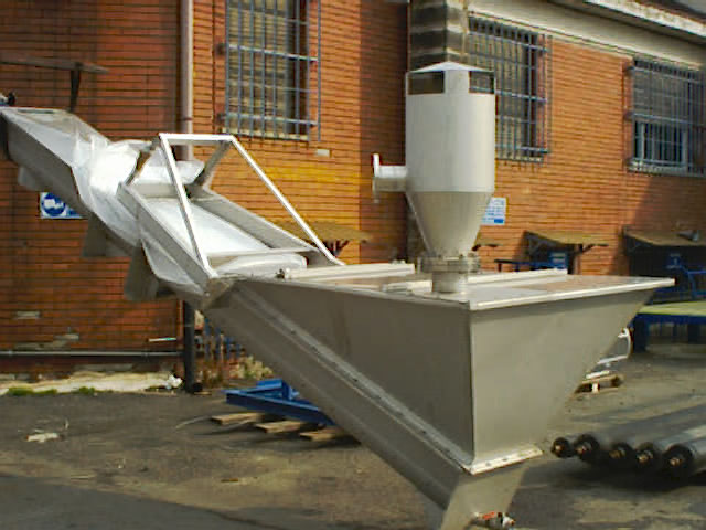
EM39 – GRIT SEPARATOR AND WASHER
| Application | Separation of sand and other solids from waste water |
| Characteristics | The machine is equipped with a screw which carries the solid materials from the channel bottom to the top. |
| Operation | Continuous |
| Materials | Compact equipment in hot dip galvanized carbon steel or stainless steel. |
| Installation | Free standing |
| Separation | Starting from 200 micron |
| Optional | Air separator for sand coming from air-lift. |
OPERATION DESCRIPTION
The water to be treated is conveyed into the feed hopper where the sand and any other solid particles decantation process takes place.
The screw lifts the solid materials from the hopper to the discharge outlet.
After having been separated from water, the sand is washed with clean water by a spraying nozzle; the dirty water returns to the tank and the washed sand is lifted by the screw.
At the first starting, before the grit is lifted and evacuated outside the machine, the solid materials must begin settling down to form a bed of grit. When a sufficiently thick bed of grit is formed, the equipment begins evacuating the solid material (grit).
TECHNICAL DATA
| Modello | EM39SF400-15 | EM39SF900-30 | EM39SF1400-50 | EM39SF2000-70 | EM39SF3000-100 | EM39SF4000-130 | |
| Portata da trattare | : m3/h | 15-20 | 30 | 50 | 70 | 100 | 130 |
| Volume tramoggia | : dm3. | 400 | 880 | 1400 | 1970 | 3000 | 3900 |
| Portata sollevabile sabbia | : m3/h | 0.3 | 0.8 | 0.8 | 0.8 | 0.8 | 1.3 |
| Diametro coclea | : mm. | 180 | 280 | 280 | 280 | 280 | 360 |
| Velocità rotazione coclea | : rpm | 5 | 5 | 5 | 5 | 5 | 10 |
| Motore elettrico | : kw. | 0.37 | 0.37 | 0.37 | 0.55 | 0.55 | 1.5 |
| Alimentazione | : V-ph-Hz | 380-3-50/60 | 380-3-50/60 | 380-3-50/60 | 380-3-50/60 | 380-3-50/60 | 380-3-50/60 |
| Poli motore | : no. | 4 | 4 | 4 | 4 | 4 | 4 |
| Protezione motore | : IP | 55 | 55 | 55 | 55 | 55 | 55 |
| Classe isolamento | : | F | F | F | F | F | F |
| Peso total macchina | : kg. | 410 | 640 | 730 | 1350 | 1750 | 1900 |
| Lunghezza coclea | : mm. | 3300 | 4100 | 4510 | 4860 | 5875 | 6000 |
| Discharge height | : mm. | 1500 | 1584 | 1750 | 1900 | 2330 | 2350 |
-
EM39 separ.aria

-
EM39 360-1400-inox

EM41
Reciprocating type grit classifier
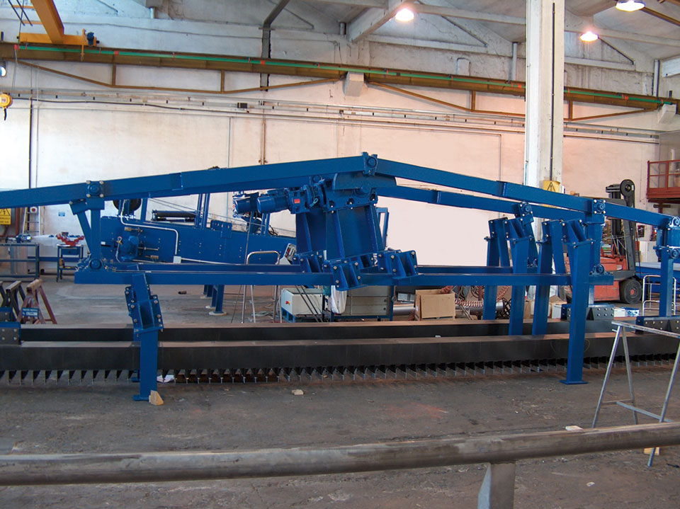
EM41 – RECIPROCATING GRIT SEPARATOR AND WASHER
| Application | Separation of sand and other solids from waste water |
| Characteristics | The machine is equipped with a series of parallel plates which lift the solid materials from the channel bottom to the top. |
| Operation | The grit settled on the bottom is dragged by the scrapers which have a reciprocating motion out of the water. Before being discharged, the grit is washed with water. |
| Materials | Compact equipment in hot dip galvanized carbon steel or stainless steel. |
| Installation | In a concrete channel. |
| Channel width | From 300 to 1500 mm. |
| Separation | Starting from 200 microns |
| Advantages | The grit scrapers do not lay on the bottom, therefore they are not subject to wear. |
OPERATION DESCRIPTION
The water to be treated is conveyed into the feed hopper where the sand and any other solid particles decantation process takes place.
The grit scrapers, thanks to their reciprocating motion, lifts the solid materials from the hopper to the discharge outlet.
After having been separated from water, the sand is washed with clean water by a spraying nozzle; the dirty water returns to the tank and the washed sand is lifted by the screw.
At the first starting, before the grit is lifted and evacuated outside the machine, the solid materials must begin settling down to form a bed of grit. When a sufficiently thick bed of grit is formed, the equipment begins evacuating the solid material (grit).
TECHNICAL DATA
| 1.1 | Waste water delivery to the grit separator | :m³/h | (*) |
| 1.2 | Suspended solids | :% | (*) |
| 1.3 | Size of the suspended solids to be separated | :micron | >200 |
| 1.4 | Channel width | :mm. | (*) |
| 1.5 | Slope | :° | 20° |
| 1.6 | Length of the channel or discharge elevation | :mm. | (*) |
| 1.7 | Scrapers stroke | :mm. | 160 |
| 1.8 | Scrapers lift | :mm. | 80 |
| 1.9 | Number of cycles per minute | :no. | 12 |
| (*) to be advised when asking for a quotation | |||
-
EM41 C04664

EM66
Oil collecting rotating pipe
EM66 – OIL SKIMMER PIPE
| Application | Evacuation of the floating material. |
| Characteristics | The equipment is made of a rotary slotted pipe and a regulation unit. |
| Material | Galvanized or stainless steel |
| Optional | Motorized control |
DESCRIPTION OF OPERATION
By turning the control handwheel in a clockwise or counterclockwise direction, a bronze nut screw on which a screw is engaged rotates too. The screw moves, upwards or downwards, together with a rack which is integral to the screw. The rack is engaged on a crown wheel which makes the oil skimmer pipe rotate.
The scraper bridge is finishing his return run with the skimming blade down and conveys the floating material towards the oil skimmer. When the skimming blade gets next to the oil skimmer, the pipe is rotated till the longitudinal slots are partially submerged and the floating material flows out. This operation can be repeated after a certain number of operation cycles or the oil skimmer pipe position can be adjusted to achieve a constant minimum, but sufficient, evacuation of the floating material. This gives rise to a surface calling effect which, also increased by the skimming blade approach, collects the floating material and conveys it out.
The following data are required to make a quotation
| 1.1 | Tank width | : m3/h |
| 1.2 | Pipe diameter | : m. |
| 1.3 | Material |
Moreover you should specify whether the oil skimmer pipe shall be manual or motorized.
EM77
Grit lifting system with air-lift pump
EM77 – AIR LIFT
| Application | Lifting of liquids even when containing a considerable amount of solid material. |
| Characteristics | The equipment is made of a lifting pipe, a lower suction unit and a top drain unit. |
| Material | Galvanized or stainless steel |
The following technical data are required to make a quotation
| 1.1 | Required capacity | : m3/h |
| 1.2 | Water level | : m. |
| 1.3 | ain height, above the water level | : m. |
There is a lower head consisting of a central pipe and external chamber for the air distribution. A series of calibrated holes homogeneously diffuse the air inside the lifting pipe. The upper head is made of a tank with cover which receives the water and air coming from the tank bottom. The aim of the upper head is the separation of air from water which is discharged through the top.
OUTLINES OF THE GRIT REMOVAL PROCESS
The waste water often contains a large quantity of inert materials, mainly inorganic, which are generally defined as grit, even if actually the quantity of sand/grit is only a part of this type of materials. In fact, in the waste water treatment field, the words “grit” or “sand” do not refer only to the siliceous sands, of various sizes, but they are more commonly intended as the group of heavy inert materials which can be found in the waste water. The greatest quantity of grit reaches the waste water treatment plant during rainy periods, also because the cities sewer systems usually have a slight slope, and then a slow speed, and the sediments are dragged when the flow rate is rising.
A good grit removal system should sediment all and only the grits, of any size. The sedimentation of the organic materials should be avoided because the presence of putriscible materials in the removed grit would make them unusable or would not allow a direct elimination because it should be thouroughly washed. Anyway in the grit removal systems, even if well sized and designed, there is always a small quantity of organic material. To achieve a good grit separation there must be some specific physical conditions which allow to exploit the phenomenon of the difference of sedimentation speed between the particles of inert material, which sediment more quickly, and the particles of organic material.
There are a few types of Grit Removal Systems: gravity grit removal systems where the grit separation is achieved only by gravity (channel type systems) mechanized grit removal systems where the grit separation is helped by the rotation of a turbine (VORTEX type systems) aerated grit removal systems where the grit separation is helped by the air blown from the bottom
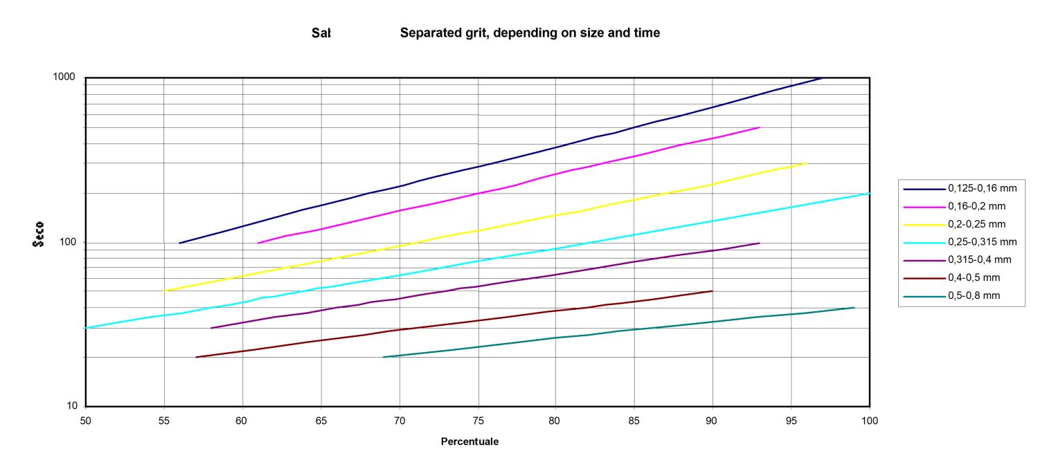
In the aerated grit removal systems the turbulence due to the air helps the grit separation and the suspension of the organic material. The addition of a vertical baffle in the aerated grit removal systems makes the oils separation easier. They are collected in a calm zone, after the baffle. The following table shows the percentage of the grit separation, depending on the granules size and the time of permanence in the tank.