Lorem ipsum dolor sit amet, consectetur adipiscing elit. Donec pretium vulputate magna, et suscipit metus interdum sit amet. In luctus et ligula et tincidunt. Etiam accumsan porta felis, eget dignissim leo venenatis id. Nullam sed risus non enim molestie volutpat. Praesent facilisis magna elit, vel ultrices elit laoreet eget. Sed dui tellus, gravida ullamcorper nisl in, cursus volutpat nisi. Proin euismod orci quis risus pharetra scelerisque. Sed sapien erat, tempor sit amet commodo at, aliquam vel magna. Nulla vestibulum neque non tempor porta.
Municipal water and wastewater screening
Civil sump screening
Industrial water and wastewater screening
| Application | Screening of civil and industrial waste water. Screening of water for hydroelecgtric power plants. Screening of water for land reclamation works. |
| Characteristics | The machine is equipped with a fixed bar screen and movable cleaning rake driven by chains installed above the water level. |
| Operation | The coarse bodies in the waste water are stopped by the bar screen. This material is removed by the cleaning rake and discharged in the upper part, out of water. The rake is guided by two lateral trolleys which are driven by two transmission chains. |
| Materials | Compact machine: hot dip galvanized carbon steel or stainless steel. The chains and the moving parts are always above the water level. |
| Installation | In a concrete channel. |
| Channel width | From 1000 to 2500 mm. |
| Degree of filtration | From 20 to 80 mm. |
| Advantages | Chains and moving parts above the water level |
| Optional | Torque limiting device to measure the cleaning rake stress with alarm and/or machine shutdown. Walkway and ladder to reach the top mechanical members. |
The machine operation is controlled by a Pause-ON timer. If the water level upstream the mechanical bar screen should increase and exceed a pre-set threshold, a level measurer can start the machine, even during the pause phase. The machine stop and the beginning of the pause phase is possible only whether the cleaning rake has reached a pre-set position out of water and the material collected has been discharged. The machine is operated by a geared motor which moves the cleaning rake. During the lowering phase, the cleaning rake is in open position and remains open as far as the lowest position is reached. When the cleaning rake reaches the bottom of the channel, the chain makes the rake get closer to the bar screen. So during the lifting phase, the rake cleans the bars and holds the screened material inside. Before the cleaning rake reaches the top position, a special device cleans its internal part and discharges the material outside, into a container or on a belt conveyor. At the top, a limit switch controls the cleaning rake operation.
| 1.1 | Design flow rate in the channel | :m³/h |
| 1.2 | Max. flow rate in the channel | :m³/h |
| 1.3 | Water max. level downstream the bar screen | :mm. |
| 1.4 | Water max. level upstream the bar screen | :mm. |
| 1.5 | Channel width | :mm. |
| 1.6 | Channel height | :mm. |
| 1.7 | Discharge elevation from the channel bottom | :mm. |
| 1.8 | Spacing between the bars | :mm. |
It is also necessary that you mention the required materials of construction.
| Application | Screening of civil and industrial waste water |
| Characteristics | The machine is equipped with a fixed bar screen and a cleaning rake controlled by an oil-pressure cylinder. |
| Operation | The coarse bodies in the waste water are stopped by the bar screen. This material is removed by the cleaning rake and discharged in the upper part, out of water. The rake is guided by two lateral trolleys which are driven by two transmission chains. The rake engagement and disengagement is controlled by an oil-pressure cylinder. |
| Materials | Compact machine: hot dip galvanized carbon steel or stainless steel. The control parts are always above the water level. |
| Installation | In a concrete channel. |
| Channel width | From 1000 to 3500 mm. |
| Degree of filtration | From 20 mm to 80 mm. |
| Advantages | Moving/control parts above the water level, high force of penetration of the cleaning rake. |
| Optional | Torque limiting device to measure the cleaning rake stress with alarm and/or machine shutdown. Walkway and ladder to reach the top mechanical members. |
The machine operation is controlled by a Pause-ON timer. If the water level upstream the mechanical bar screen should increase and exceed a pre-set threshold, a level measurer can start the machine, even during the pause phase. The machine stop and the beginning of the pause phase is possible only whether the cleaning rake has reached a pre-set position out of water and the material collected has been discharged. The machine is operated by a geared motor which moves the cleaning rake (lifting and lowering) and an oil-pressure unit for a strong engagement and disengagement of the rake. During the lowering phase, the cleaning rake is in open position and remains open as far as the lowest position is reached. When the cleaning rake reaches the bottom of the channel, a limit switch stops it. The oil-pressure piston makes the rake get deeply into the spaces between bars, then the geared motor receives a re-start signal and lifts the cleaning rake to the discharge point. The piston is equipped with two internal proximity sensors which allow the total use of its stroke. During the lifting phase, the rake cleans the bars and holds the screened material inside. Before the cleaning rake reaches the top position, a special device cleans its internal part and discharges the material outside, into a container or on a belt conveyor. At the top, a limit switch stops the motor and reverses the motion to make the cleaning rake go down again. Meanwhile, the oil-pressure cylinder has taken the rake out of the screen.
| 1.1 | Design flow rate in the channel | :m³/h |
| 1.2 | Max. flow rate in the channel | :m³/h |
| 1.3 | Water max. level downstream the bar screen | :mm. |
| 1.4 | Water max. level upstream the bar screen | :mm. |
| 1.5 | Channel width | :mm. |
| 1.6 | Channel height | :mm. |
| 1.7 | Discharge elevation from the channel bottom | :mm. |
| 1.8 | Spacing between the bars | :mm. |
It is also necessary that you mention the required materials of construction.
| Utilizzo | Grigliatura acque di scarico civili ed industriali |
| Caratteristiche | La macchina è costituita da una griglia fissa e da una benna comandata da due gruppi di comando, uno per la movimentazione verticale e l’altro per l’apertura e chiusura della stessa. |
| Funzionamento | I corpi grossolani sono intercettati dalla griglia. Il materiale grigliato è asportato dalla benna mobile e scaricato nella parte superiore fuori acqua. La benna è guidata da due carrelli, che sono movimentati da due sistemi a fune (uno per il movimento verticale e l’altro per l’apertura e la chiusura ). |
| Costruzione | Macchina compatta in acciaio zincato o inossidabile. Gli organi di comando sono sempre fuori acqua |
| Installazione | In canale di calcestruzzo. |
| Larghezza del canale | Da 1000 a 3000 mm. |
| Grado di filtrazione | Da 15 a 100 mm. |
| Vantaggi | Adatta per canali molto profondi, con presenza di sabbia sul fondo e solidi di grosse dimensioni. |
| Svantaggi | Non adatta per canali di piccole dimensioni. |
| Opzioni | Cella dinamometrica per misurare lo sforzo del pettine pulitore con allarme e/o blocco griglia. Passerella e scala per accedere agli organi meccanici posti superiormente. |
La macchina è comandata da un timer pausa-lavoro. Qualora il livello dell’acqua a monte della griglia aumentasse superando una determinata soglia, un misuratore di livello può imporre il riavvio della griglia anche se questa è in fase di pausa. La fermata in pausa della macchina avviene solo se la benna ha raggiunto una determinata posizione fuori acqua ed a scarico avvenuto. La macchina è azionata da 2 motoriduttori, uno aziona il sollevamento del pettine pulitore e l’altro aziona il gruppo di inserimento e disinserimento del pettine nella griglia. Nella parte superiore del gruppo di comando vi sono 3 tamburi: 2 laterali ed uno centrale. I tamburi sono comandati da un motoriduttore ed avvolgono e svolgono le funi che sollevano ed abbassano il pettine pulitore. Il secondo motoriduttore aziona una puleggia che avvolge e svolge la fune centrale provocando l’avvicinamento e l’ allontanamento della benna dalla griglia. Nella fase di discesa del carrello , la benna è in posizione di apertura fino a quando viene raggiunta la posizione più bassa. Quando la benna appoggia sul fondo, la fune di traino si allenta ed interviene un fine corsa (collegato sul tiro della fune) a bloccare il motoriduttore. Si inverte il senso di rotazione del 1° motoriduttore e si aziona il secondo motoriduttore che avvolge la fune centrale, così facendo la benna si impegna nella griglia. Avviene quindi la fase di risalita durante la quale la benna pulisce la griglia e trattiene lo sgrigliato all’interno. Prima che la benna raggiunga la posizione superiore, un apposito dispositivo provvede a pulirne la parte interna ed a scaricare il materiale in un cassonetto o su di un nastro trasportatore. Nel punto superiore un fine corsa ferma il motore che aziona il sollevamento della griglia e ne inverte il moto iniziando la corsa di discesa. Nel frattempo il 2°motoriduttore aziona il tamburo centrale che allontana il pettine pulitore dalla griglia. La corsa di discesa avviene con la benna distanziata dalla griglia.
| 1.1 | Portata canale di progetto | :m³/h |
| 1.2 | Portata nel canale max | :m³/h |
| 1.3 | Altezza massima dell’ acqua a valle della griglia | :mm. |
| 1.4 | Altezza massima dell’ acqua a monte della griglia | :mm. |
| 1.5 | Larghezza canale | :mm. |
| 1.6 | Altezza canale | :mm. |
| 1.7 | Altezza di scarico da fondo canale | :mm. |
| 1.8 | Luce libera tra le barre | :mm. |
È inoltre necessario specificare i materiali con cui sarà costruita la macchina
| Application | Screening of civil and industrial waste water |
| Characteristics | The machine is equipped with a fixed bar screen and a bucket controlled by two drive units, one for the vertical motion and one for the opening and closing. |
| Operation | The coarse bodies in the waste water are stopped by the bar screen. This material is removed by the moving bucket and discharged in the upper part, out of water. The bucket is guided by two trolleys which are driven by two cable systems (one for the vertical motion and one for the opening and closing). |
| Materials | Compact machine: hot dip galvanized carbon steel or stainless steel. The control parts are always above the water level. |
| Installation | In a concrete channel. |
| Channel width | From 1000 to 3000 mm. |
| Degree of filtration | From 15 to 100 mm. |
| Advantages | Suitable for very deep channels, even with sand on the bottom and/or large size solids. |
| Disadvantages | Not suitable for small or shallow channels. |
| Optional | Torque limiting device to measure the bucket/rake stress with alarm and/or machine shutdown. Walkway and ladder to reach the top mechanical members. |
The machine operation is controlled by a Pause-ON timer. If the water level upstream the mechanical bar screen should increase and exceed a pre-set threshold, a level measurer can start the machine, even during the pause phase. The machine stop and the beginning of the pause phase is possible only whether the bucket has reached a pre-set position out of water and the material collected has been discharged. The machine is controlled by no. 2 geared motors, one for the bucket lifting and lowering and the second one for its engagement into the bar screen and then for its disengagement. In the drive unit upper part, there are no. 3 drums (no. 2 side drums + no. 1 central drum). They are driven by a geared motor and they wind and unwind the cables which lift and lower the screening bucket/rake. The second geared motor operates a pulley which controls the bucket/rake operation by winding and unwinding the central cable. During the lowering phase, the bucket is in open position and remains open as long as the lowest position is reached. When the bucket lays on the bottom, the traction cable is loosened and a limit switch intervenes to stop the motor (this limit switch is connected to the cable). Then, the first geared motor rotation direction is reversed, the second geared motor starts up to wind the central cable and the bucket/rake is inserted into the bar screen. So the bucket/rake is lifted again and during the lifting phase it cleans the bar screen and holds the screened material inside. Before the bucket gets to the top position, it is cleaned by a special device and the screened material is discharged outside, into a container or on a belt conveyor. At the top, a limit switch stops the motor and reverses the motion to make the bucket go down again. Meanwhile, the second geared motor moves the central drum which separates the screening rake from the bar screen. During the lowering phase, the bucket/rake remains far from the bar screen.
| 1.1 | Design flow rate in the channel | :m³/h |
| 1.2 | Max. flow rate in the channel | :m³/h |
| 1.3 | Water max. level downstream the bar screen | :mm. |
| 1.4 | Water max. level upstream the bar screen | :mm. |
| 1.5 | Channel width | :mm. |
| 1.6 | Channel height | :mm. |
| 1.7 | Discharge elevation from the channel bottom | :mm. |
| 1.8 | Spacing between the bars | :mm. |
It is also necessary that you mention the required materials of construction.
| Application | Screening of civil and industrial waste water |
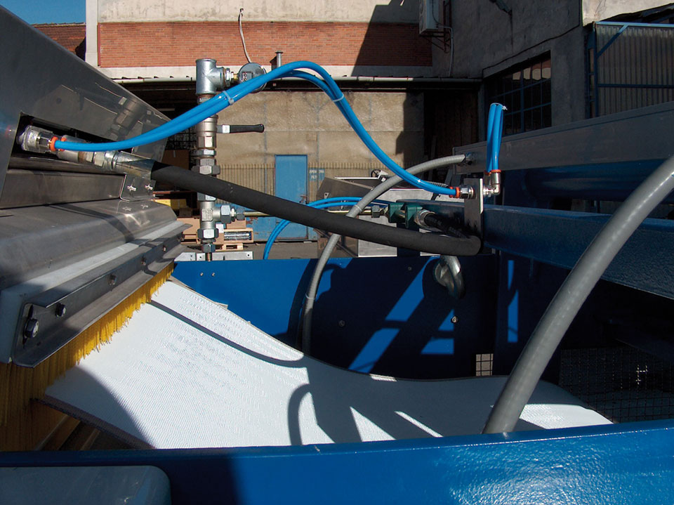
| Characteristics | The machine is equipped with a filtering continuous belt made of acetalic resin elements (teeth+rollers) and stainless steel shafts. Cleaning brush and washing system. |
| Operation | The waste water containing suspended particles goes through the filtering elements which hold the material in suspension. This material is lifted and removed by a rotary cleaning brush and a washing system. |
| Materials | Compact machine: stainless steel. |
| Installation | In a concrete channel. |
| Channel width | From 300 to 2000 mm. |
| Degree of filtration | 3 or 6 mm. |
| Advantages | Continuous filtration, suitable even for water containing filaments of fibers. |
| Disadvantages | Not suitable to remove solid materials larger than 250 mm.. |
| Optional | Electromagnetic coupling with alarm sensor. Double cleaning brush (motorized). |
The machine operation is controlled by a Pause-ON timer. If the water level upstream the filtering screen should increase and exceed a pre-set threshold, a level measurer can start the machine, even during the pause phase. The filtering belt lifts continuously the solids held by the plastic material elements. At the top, the screened material is discharged thanks to the teeth movement, a rotary brush and two washing systems which furtherly take off the screened material.
The grit in the water may wear the rollers placed on the cleaning teeth supporting shafts sides. The rollers shafts are protected against wear by some bushes fixed to the shafts. The rollers are made of plastic material, are low cost as mass-produced and can be easily replaced.
The sliding guides for the chains are bolted to the frame and can be easily replaced.
| 1.1 | Design flow rate in the channel | :m³/h |
| 1.2 | Max. flow rate in the channel | :m³/h |
| 1.3 | Water max. level downstream the bar screen | :mm. |
| 1.4 | Water max. level upstream the bar screen | :mm. |
| 1.5 | Channel width | :mm. |
| 1.6 | Channel height | :mm. |
| 1.7 | Discharge elevation from the channel bottom | :mm. |
| 1.8 | Spacing between the filtering elements | :mm. |
The materials of construction used are: stainless steel for the frame and shafts; acetalic resin for the filtering teeth and the rollers.
| Application | Screening of civil and industrial waste water. Screening of process water within industrial cycles. |
| Characteristics | The machine is equipped with a fixed basket made of trapezoidal bars or perforated plate, a lifting screw with cleaning brushes, a compactor and a washing system for the screened material. |
| Operation | The waste water containing suspended particles goes through the filtering basket which holds the material in suspension. This material is lifted and removed by a screw equipped with cleaning brushes on the profile in contact with the basket. The screened material is washed by washing ramps, located in three different positions. |
| Materials | Compact machine: stainless steel. |
| Installation | In a concrete or stainless steel channel |
| Channel width | From 370 to 750 mm. |
| Degree of filtration | From 0.5 to 10 mm. |
| Advantages | Continuous filtration, suitable even for water containing filaments of fibers. |
| Disadvantages | Not suitable to remove solid materials larger than 250 mm |
The machine operation is controlled by a Pause-ON timer. If the water level upstream the filtering screen should increase and exceed a pre-set threshold, a level measurer can start the machine, even during the pause phase. The water to be treated is filtered by the fixed basket and the solids held are lifted, compacted and discharged by a screw. During the lifting, the screened material is washed to remove the soluble organic substances.
| 1.1 | Design flow rate in the channel | :m³/h |
| 1.2 | Max. flow rate in the channel | :m³/h |
| 1.3 | Water max. level downstream the bar screen | :mm. |
| 1.4 | Water max. level upstream the bar screen | :mm. |
| 1.5 | Channel width | :mm. |
| 1.6 | Channel height | :mm. |
| 1.7 | Discharge elevation from the channel bottom | :mm. |
| 1.8 | Spacing of filtration | :mm. |
The material of construction used is normally stainless steel.
| Utilizzo | Screening of civil and industrial waste water. |
| Characteristics | The machine consists of a rotary drum. |
| Operation | The coarse solids are retained and remain outside the rotary drum. Then this material is removed by a cleaning scraper and the drum is washed by a washing system located inside the drum. |
| Materials | Compact machine: stainless steel. |
| Installation | Out of the channel. |
| Diametro del tamburo | 628 or 920 mm |
| Lunghezza del tamburo | From 500 to 3000 mm |
| Degree of filtration | From 0,25 to 3 mm. |
| Disadvantages | Cleaning brush. |
The machine operation is controlled by a Pause-ON timer. If the water level in the tank of the water to be treated should increase and exceed a pre-set threshold, a level measurer can start the machine, even during the pause phase. The water to be treated goes to the feed tank and is distributed all over the drum surface. The machine is operated by a geared motor which controls its rotation. The filtration process occurs from outside to inside the drum, so the filtered water comes out from inside the drum and keeps it continuously clean. The solid material which remains outside the drum is scraped by a cleaning scraper which can be helped by a motorized brush which can be provided as an optional accessory. The feeding is made by gravity or by means of a pump.
Table of capacities (m3>/h) with a quantity of SST = 200 ppm
| Spacing of filtration | |||||||||
| Model | 0,25 | 0,5 | 0,75 | 1,0 | 1,25 | 1,5 | 2 | 2,5 | 3 |
| EM79-6005 | 45 | 80 | 105 | 125 | 140 | 155 | 180 | 195 | 210 |
| EM79-6006 | 55 | 95 | 125 | 150 | 170 | 190 | 210 | 235 | 250 |
| EM79-6007 | 65 | 110 | 150 | 180 | 200 | 220 | 250 | 280 | 300 |
| EM79-6008 | 75 | 125 | 170 | 205 | 230 | 255 | 290 | 320 | 340 |
| EM79-6010 | 90 | 160 | 215 | 260 | 290 | 320 | 370 | 405 | 430 |
| EM79-6015 | 135 | 240 | 325 | 395 | 450 | 490 | 555 | 610 | 650 |
| EM79-6020 | 180 | 300 | 435 | 530 | 590 | 650 | 750 | 820 | 870 |
| EM79-9030 | 435 | 740 | 980 | 1250 | 1450 | 1650 | 1850 | 2150 | 2350 |
| Application | Screening of civil and industrial waste water. |
| Characteristics | The machine is equipped with a continuous-cycle filtering belt. |
| Operation | The coarse solids are retained by the belt and discharged into a container, out of the machine. The belt is brushed and washed with water. |
| Materials | Compact machine: stainless steel. |
| Installation | Out of the channel. |
| Belt width | 1200 – 2100 – 3000 mm |
| Degree of filtration | From 150 microns to 2 mm.. |
| Advantages | Continuous filtration, suitable for water containing grease, filaments of fibers and any substances which tend to clog the normal rotary drum screens. |
| Opzioni | High pressure washing system.e |
The machine operation is controlled by a Pause-ON timer. According to the type of application, the machine operation can be controlled by a level measurer placed in the feed tank or by a sensor in the feed or drain pipe. The water to be treated goes to the feed tank and is distributed all over the belt surface. The machine is operated by a geared motor which controls its rotation. The filtration occurs by gravity and the solid material retained by the filtering belt is removed by a system of motorized rotary brushes. After the removal of the retained material, the belt is washed in continuous by means of a washing system using water. This keeps the belt always clean. The feeding is made by gravity or by means of a pump.
| 1.1 | Feed flow rate | : m³/hr | |||
| 1.1 | Suspended solids in the water to be treated | : p.p.m. | |||
| 1.2 | Minimum size of the solids to be separated | : micron | |||
| 1.3 | Model to be used | : EM | 100/1200 | 100/2100 | 100/3000 |
| 1.4 | Filtering belt width | : mm | 1200 | 2100 | 3000 |
| 1.5 | Filtering belt speed | : mt/min. | 1,6-8,5 | 1,6-8,5 | 1,6-8,5 |
| 1.6 | Maximum opening of the filtering meshes | : micron | |||
| Services required | |||||
| Wash water | |||||
| 1.7 | Flow rate | : m3/hr | 1,2 | 2 | 3 |
| 1.8 | Head | : Bar | 20 | 20 | 20 |
| Compressed air | |||||
| 1.9 | Flow rate | : lt/min. | 250 | 250 | 250 |
| 1.10 | Pressure | : Bar | 7 | 7 | 7 |
| Electric equipments | |||||
| 1.11 | Belt drive | : Kw 0,55 | 0,75 | 1,5 | |
| 1.12 | Cleaning brush | : Kw | 0,37 | 0,37 | 0,37 |
| 1.13 | High pressure water pump (optional) | : Kw | 4 | 5,5 | 7,5 |
| 1.14 | Air compressor | : Kw | 2,2 | 2,2 | 2,2 |
| 1.15 | Submersible pump for washwater evacuation | : Kw 0,55 | 0,75 | 1,1 | |
The material of construction used is normally stainless steel.
| Application | Evacuation of dewatered sludge or screened material. |
| Characteristics | The machine is equipped with a rotary screw which carries the solid material. |
| Material | Painted or galvanized or stainless steel. |
| Modelli | EM49 A1 Horizontal screw with shaft EM49 A2 Inclined fixed screw with shaft EM49 A3 Inclined swinging screw with shaft EM49 A4 R/L Horizontal screw with shaft EM49 B1 Horizontal shaftless screw EM49 B2 Inclined fixed shaftless screw EM49 B3 Inclined swinging shaftless screw EM49 B4 R/L shaftless horizontal screw |
| 1.1 | Length | : m3 | |
| 1.2 | Screw diameter | : mm | 500 |
| 1.3 | Load height | : m | |
| 1.4 | Discharge height | : m | |
| 1.5 | Required capacity |
| plication | Evacuation of dewatered sludge or screened material. |
| Characteristics | The machine is equipped with a movable belt which carries the solid material. |
| Material | Painted or galvanized or stainless steel. |
| Modelli | EM62 A Horizontal EM62 B Inclined and fixed EM 62 C Inclined and swinging EM 62 D Goose neck |
| Sicurezze | Safety cable on both sides of the machine. |
| 1.1 | Length | : m3 | |
| 1.2 | Belt width | : mm | 500 |
| 1.3 | Load height | : m | |
| 1.4 | Discharge height | : m | |
| 1.5 | Required capacity | : kg/h |
| Application | Screened material conveying and compaction. |
| Characteristics | The machine is equipped with a conveying screw and a compacting unit. |
| Operation | The screened material is conveyed in the compacting unit by the screw, the separated water returns to the channel. |
| Materials | Compact machine: stainless steel. |
| Installation | Out of the channel. |
| Lunghezza della spirale | Variable |
The screened material is conveyed by the screw to the compacting unit equipped with a draining basket and a discontinuous washing. Then it is compacted and discharged. The drained water returns to the channel.
| 1.1 | Machine channel width | : mm. | 225 |
| 1.2 | Screw external diameter | : mm. | 180 |
| 1.3 | Screw internal diameter | : mm. | 105 |
| 1.4 | Capacity | : m3/h | 2 |
| 1.5 | Slope | : ° | 5° |
| 1.6 | Screw number of revolutions | : r.p.m. | 28 |
| 1.7 | eened material elevation discharge | : mm. | |
| 1.8 | Screw length | : mm. | |
| 1.9 | Total length | : mm. | |
| 1.10 | Washwater flow rate | : mc/h | 1-2 |
| 1.11 | Power | : Kw. | 1,5 |
| 1.12 | Tension | : V-f-Hz | 380-3-50 |
| 1.13 | Motor protection | : IP | 55 |
The material of construction used is normally stainless steel.
| Application | Screened material conveying and compaction. |
| Characteristics | The machine is equipped with a load chamber with piston, a compactor and discharge pipe and an oil-pressure unit. |
| Operation | The screened material is collected in the load chamber, the piston has an alternative movement, during the forward stroke it compacts and conveys the material into the discharge pipe. |
| Materials | Compact machine: stainless steel. |
| Installation | Out of the channel. |
| Diametro del pistone | 250 mm or 350 mm |
| 1.1 | Conveying Press | |||
| 1.1.1 | Capacity | : mc/h. | 1,8 | 2,7 |
| 1.1.2 | Cylinder diameter | : mm. | 250 | 350 |
| 1.1.3 | Max. specific pressure | :kg/cmq | 15 | 10 |
| 1.1.4 | Feed inlet size | : mm. | 500×350 | 600×450 |
| 1.1.5 | Compacted material outlet flange | : DN | 250 | 350 |
| 1.1.6 | Separated water drainage flange | : “ | 2 | 2 |
| 1.1.7 | Material | : AISI | 304 | 304 |
| 1.2 | Oil-Pressure Unit | |||
| 1.2.1 | Power | : kW | 4 | 5,5 |
| 1.2.2 | Pump capacity | : lt/1’ | 8 | 10 |
| 1.2.3 | Oil tank capacity | : lt. | 60 | 60 |
| 1.2.4 | Max. push pressure | : BAR | 200 | 200 |
| 1.3 | Piston | |||
| 1.3.1 | Bore | :mm | 80 | 100 |
| 1.3.2 | Stroke | :mm | 700 | 700 |
| 1.3.3 | Stem diameter | :mm | 40 | 60 |
| 1.3.3 | Force at a pressure of 200 bar. | : kg. | 7.400 | 9700 |
Among the phenomena of backed up outflow, we have also the passage through bar screens (the bars length is placed in the stream flowing direction). The bars may have different sections and angles of inclination (α) on the horizontal line (Picture FG1). The head loss through a bar screen is determined by means of the KIRSHMER’s formula:

where: – v : water velocity without the bar screen; – α: angle of inclination of the bar screen on the horizontal line; – d : bars thickness; – a: spacing between the bars; – β: coefficient of shape, function of the bar section, as shown in the picture.
Basically, the value:

represents a head loss which causes a “backup” of water upstream or downstream the bar screen, according to whether the stream speed is slow or fast.


Indicative values of the head losses through mechanical bar screens having different spacings and an inclination of 60°
EM31C BarreCurve
EM31G 200
EM31G Ovada4
EM31G Ovada5
EM31G100 Dégrilleur
EM31G100 Messico
EM31G Rondella2
EM31G Tipico
EM32A KSA AlKumrah C3023
EM32C C5455
EM32C Italy Avezzano C5286
EM32C Kuwait Napoli C5279
EM32D 000-R0
EM32D C04487-Tunisia
EM32D Lehavim1
EM32D
EM32D1
EM32D Tunisia Ghedir C5439-1
EM32D Tunisia Ghedir C5439-2
EM32D Tunisia Ghedir C5439
EM32H 11partic
EM32H 6partic
EM32H 7
EM32H 9partic
EM32H C04800-1
EM32H Pettine
em31c
em31g acea-1
em32h 4
Municipal water and wastewater grit removal
Industrial water and wastewater grit removal
| Application | Grit and oil removal from municipal and industrial waste water. |
| Characteristics | Longitudinal flow channel, with tapered section (downwards). The channel is divided into two zones: the grit removal zone (normally aerated) the oil removal zone. The two zones are separated by a longitudinal baffle. |
| Operation | The waste water goes through the grit removal system longitudinally; the grit which sediments on the bottom is scraped and conveyed into a hopper and then lifted by air-lifts or submersible pumps. The floating substances in the oil removal zone are conveyed to the hopper by a surface scraper. |
| Materials | Compact equipment in hot dip galvanized carbon steel or stainless steel. |
| Installation | In a concrete channel. |
| Separation | Grit particles larger than 200 microns. |
| Optional | Separation between grit removal-oil removal zones. Power supply by cable winding reel. Air blowing system. |
The water speed in the grit removal channel is lower than 0.3 m/sec., therefore the grit having a larger size than 200 microns settles on the bottom. The air distributed by the diffusers fluidifies the grit before it sediments and removes the organic substances which deposit on it. These organic substances and the other substances in the water, thanks to the air effect, float and flow together to the oil removal zone which is on the channel side and is not aerated, then they are taken away by a surface scraper. The grit settled on the bottom is conveyed to the hopper by the bottom scraper. The recommended air delivery is of 10-15 Nm3/h per metre of length of the grit removal channel.
| 1.1 | Max. flow rate in the channel | :m³/h | (*) |
| 1.2 | Width of the grit removal zone | :mm. | (*) |
| 1.3 | Width of the oil removal zone | :mm. | (*) |
| 1.4 | Channel length | :mm. | (*) |
| 1.5 | Aeration zone air flow rate | :m³/h | |
| (*) To be advised when asking for a quotation | |||
| Application | Grit and oil removal from municipal and industrial waste water. |
| Characteristics | Longitudinal flow channel, with tapered section (downwards). The channel is divided into two zones: the grit removal zone (normally aerated) the oil removal zone. The two zones are separated by a longitudinal baffle. |
| Operation | The waste water goes through the grit removal system longitudinally; the grit which sediments on the bottom is lifted and conveyed to a lateral channel by air-lifts or submersible pumps. The floating substances in the oil removal zone are conveyed to the hopper by a surface scraper. |
| Materials | Compact equipment in hot dip galvanized carbon steel or stainless steel. |
| Installation | In a concrete channel. |
| Separation | Grit particles larger than 200 microns. |
| Grit lifting systems | Air-lift Submersible pump Vertical pump |
| Optional | Separation between grit removal-oil removal zones. Power supply by cable winding reel. Air blowing system. |
The water speed in the grit removal channel is lower than 0.3 m/sec., therefore the grit having a larger size than 200 microns settles on the bottom. The air distributed by the diffusers fluidifies the grit before it sediments and removes the organic substances which deposit on it. These organic substances and the other substances in the water, thanks to the air effect, float and flow together to the oil removal zone which is on the channel side and is not aerated, then they are taken away by a surface scraper. The grit settled on the bottom is lifted by a submersible pump or air-lift and conveyed to the lateral channel. The recommended air delivery is of 10-15 Nm3/h per metre of length of the grit removal channel.
| 1.1 | Max. flow rate in the channel | :m³/h | (*) |
| 1.2 | Width of the grit removal zone | :mm. | (*) |
| 1.3 | Width of the oil removal zone | :mm. | (*) |
| 1.4 | Channel length | :mm. | (*) |
| 1.5 | Aeration zone air flow rate | :m³/h | |
| (*) to be advised when asking for a quotation | |||
| Application | Grit and oil removal from municipal and industrial waste water. |
| Characteristics | The system is made up of a turbine and an air-lift. |
| Operation | The water to be treated goes through the grit removal system with a tangential flow; the grit which sediments on the bottom is lifted by an air-lift. |
| Materials | Compact equipment in hot dip galvanized carbon steel or stainless steel. |
| Installation | In a concrete channel. |
| Tank diameter | From 1000 to 5000 mm. |
| Separation | Grit particles larger than 200 microns. |
| Advantages | The grit moved by the turbine is partially separated from the organic substances. |
| Disadvantages | Limited capacity of treatment. It does not include any oil removal system. |
| Optional | Blower |
The water flows into the grit removal tank in a tangential way and the blades keep the liquid in motion at any level of flow rate. The tangential flow and the blades rotation make the grit particles sediment on the bottom. The grit is lifted by an air-lift and is conveyed to a mechanical separator or to a simple draining and filtering bed. The grit removed is clean enough thanks to the separation of the organic substances due to the effect of the rotary blades.
Sometimes, to avoid the arising of decomposition phenomena due to the inevitable presence of organic material, a certain number of washings by water or air are necessary before extracting the grit.
This type of grit removal system does not separate any oily substances.
| 1.1 | Waste water delivery to the grit removal system | :m³/h | (*) |
| 1.2 | Useful diameter | :mm. | |
| 1.3 | Water and sand flow rate in the air-lift | :m³/h | (*) |
| 1.4 | Air-lift size | :DN. | |
| 1.5 | Rotation speed | :rpm | 30 |
| (*) to be advised when asking for a quotation | |||
| Application | Grit and oil removal from municipal and industrial waste water. |
| Characteristics | The system is made up of a separation cylinder, air diffusers and an air-lift. |
| Operation | The water to be treated goes through the grit removal system with a tangential flow; the grit which sediments on the bottom is lifted by an air-lift. The oily substances which float due to the effect of the air blowing are evacuated by means of a valve, normally with a manual control. |
| Materials | Compact equipment in hot dip galvanized carbon steel or stainless steel. |
| Installation | In a concrete tank. |
| Tank diameter | From 1000 to 5000 mm. |
| Separation | Grit particles larger than 200 microns. |
| Advantages | It is equipped with oil removal system. |
| Disadvantages | Limited capacity of treatment |
The water flows into the grit removal tank in a tangential way. The tangential flow helps the grit particles sedimentation on the tank bottom. Normally the suspension remains in the tank more than 30 seconds. The flotation of the organic substances is due to the air blowing. The grit is lifted by an air-lift and is conveyed to a mechanical separator or to a simple draining and filtering bed. The oils flow together outside the separation ring and are regularly removed by means of a manual blade or gate valve. The grit removed is clean enough thanks to the separation of the organic substances due to the effect of the air blowing.
To avoid the arising of decomposition phenomena due to the inevitable presence of organic material, a certain number of washings by water are necessary before extracting the grit.
| 1.1 | Waste water delivery to the grit removal system | :m³/h | (*) |
| 1.2 | Useful diameter | :mm. | |
| 1.3 | Water and sand flow rate in the air-lift | :m³/h | (*) |
| 1.4 | Air-lift size | :DN. | |
| 1.5 | Air flow rate | :Nm³/h | |
| (*) to be advised when asking for a quotation | |||
| Application | Grit removal from municipal and industrial waste water. |
| Characteristics | The system is equipped with baffles and grit scrapers. |
| Operation | The water to be treated goes through the grit removal system with a laminar flow; the grit which sediments on the bottom is conveyed to the sides and evacuated by an air-lift. |
| Materials | Compact equipment in hot dip galvanized carbon steel or stainless steel. |
| Installation | In a concrete tank. |
| Tank diameter | From 2000 to 16000 mm. |
| Separation | Grit particles larger than 200 microns. |
| Optional | Air-lift for grit evacuation |
The water flows into the grit removal tank from the side. The water flow must have a laminar motion. The baffles placed at the entry are installed in such a way to distribute the water homogeneously, all over the tank width.
The grit which sediments on the bottom is scraped and conveyed to the periphery of the tank where it is lifted and evacuated by an air-lift. The average water level in the tank is 700-1000 mm.
| 1.1 | Waste water delivery to the grit removal system | :m³/h | (*) |
| 1.2 | Width x length | :mm. | |
| 1.3 | Water and sand flow rate in the air-lift | :m³/h | (*) |
| 1.4 | Air-lift size | :DN. | |
| 1.5 | Rotation speed of the scrapers | :rpm | |
| (*) to be advised when asking for a quotation | |||
| Application | Separation of sand and other solids from waste water |
| Characteristics | The machine is equipped with a screw which carries the solid materials from the channel bottom to the top. |
| Operation | Continuous |
| Materials | Compact equipment in hot dip galvanized carbon steel or stainless steel. |
| Installation | Free standing |
| Separation | Starting from 200 micron |
| Optional | Air separator for sand coming from air-lift. |
The water to be treated is conveyed into the feed hopper where the sand and any other solid particles decantation process takes place.
The screw lifts the solid materials from the hopper to the discharge outlet.
After having been separated from water, the sand is washed with clean water by a spraying nozzle; the dirty water returns to the tank and the washed sand is lifted by the screw.
At the first starting, before the grit is lifted and evacuated outside the machine, the solid materials must begin settling down to form a bed of grit. When a sufficiently thick bed of grit is formed, the equipment begins evacuating the solid material (grit).
| Modello | EM39SF400-15 | EM39SF900-30 | EM39SF1400-50 | EM39SF2000-70 | EM39SF3000-100 | EM39SF4000-130 | |
| Portata da trattare | : m3/h | 15-20 | 30 | 50 | 70 | 100 | 130 |
| Volume tramoggia | : dm3. | 400 | 880 | 1400 | 1970 | 3000 | 3900 |
| Portata sollevabile sabbia | : m3/h | 0.3 | 0.8 | 0.8 | 0.8 | 0.8 | 1.3 |
| Diametro coclea | : mm. | 180 | 280 | 280 | 280 | 280 | 360 |
| Velocità rotazione coclea | : rpm | 5 | 5 | 5 | 5 | 5 | 10 |
| Motore elettrico | : kw. | 0.37 | 0.37 | 0.37 | 0.55 | 0.55 | 1.5 |
| Alimentazione | : V-ph-Hz | 380-3-50/60 | 380-3-50/60 | 380-3-50/60 | 380-3-50/60 | 380-3-50/60 | 380-3-50/60 |
| Poli motore | : no. | 4 | 4 | 4 | 4 | 4 | 4 |
| Protezione motore | : IP | 55 | 55 | 55 | 55 | 55 | 55 |
| Classe isolamento | : | F | F | F | F | F | F |
| Peso total macchina | : kg. | 410 | 640 | 730 | 1350 | 1750 | 1900 |
| Lunghezza coclea | : mm. | 3300 | 4100 | 4510 | 4860 | 5875 | 6000 |
| Altezza di scarico | : mm. | 1500 | 1584 | 1750 | 1900 | 2330 | 2350 |
| Application | Separation of sand and other solids from waste water |
| Characteristics | The machine is equipped with a series of parallel plates which lift the solid materials from the channel bottom to the top. |
| Operation | The grit settled on the bottom is dragged by the scrapers which have a reciprocating motion out of the water. Before being discharged, the grit is washed with water. |
| Materials | Compact equipment in hot dip galvanized carbon steel or stainless steel. |
| Installation | In a concrete channel. |
| Channel width | From 300 to 1500 mm. |
| Separation | Starting from 200 microns |
| Advantages | The grit scrapers do not lay on the bottom, therefore they are not subject to wear. |
The water to be treated is conveyed into the feed hopper where the sand and any other solid particles decantation process takes place.
The grit scrapers, thanks to their reciprocating motion, lifts the solid materials from the hopper to the discharge outlet.
After having been separated from water, the sand is washed with clean water by a spraying nozzle; the dirty water returns to the tank and the washed sand is lifted by the screw.
At the first starting, before the grit is lifted and evacuated outside the machine, the solid materials must begin settling down to form a bed of grit. When a sufficiently thick bed of grit is formed, the equipment begins evacuating the solid material (grit).
| 1.1 | Waste water delivery to the grit separator | :m³/h | (*) |
| 1.2 | Suspended solids | :% | (*) |
| 1.3 | Size of the suspended solids to be separated | :micron | >200 |
| 1.4 | Channel width | :mm. | (*) |
| 1.5 | Slope | :° | 20° |
| 1.6 | Length of the channel or discharge elevation | :mm. | (*) |
| 1.7 | Scrapers stroke | :mm. | 160 |
| 1.8 | Scrapers lift | :mm. | 80 |
| 1.9 | Number of cycles per minute | :no. | 12 |
| (*) to be advised when asking for a quotation | |||
| Application | Evacuation of the floating material. |
| Characteristics | The equipment is made of a rotary slotted pipe and a regulation unit. |
| Material | Galvanized or stainless steel |
| Optional | Motorized control |
By turning the control handwheel in a clockwise or counterclockwise direction, a bronze nut screw on which a screw is engaged rotates too. The screw moves, upwards or downwards, together with a rack which is integral to the screw. The rack is engaged on a crown wheel which makes the oil skimmer pipe rotate.
The scraper bridge is finishing his return run with the skimming blade down and conveys the floating material towards the oil skimmer. When the skimming blade gets next to the oil skimmer, the pipe is rotated till the longitudinal slots are partially submerged and the floating material flows out. This operation can be repeated after a certain number of operation cycles or the oil skimmer pipe position can be adjusted to achieve a constant minimum, but sufficient, evacuation of the floating material. This gives rise to a surface calling effect which, also increased by the skimming blade approach, collects the floating material and conveys it out.
| 1.1 | Tank width | : m3/h |
| 1.2 | Pipe diameter | : m. |
| 1.3 | Material |
Moreover you should specify whether the oil skimmer pipe shall be manual or motorized.
| Application | Lifting of liquids even when containing a considerable amount of solid material. |
| Characteristics | The equipment is made of a lifting pipe, a lower suction unit and a top drain unit. |
| Material | Galvanized or stainless steel |
| 1.1 | Required capacity | : m3/h |
| 1.2 | Water level | : m. |
| 1.3 | ain height, above the water level | : m. |
There is a lower head consisting of a central pipe and external chamber for the air distribution. A series of calibrated holes homogeneously diffuse the air inside the lifting pipe. The upper head is made of a tank with cover which receives the water and air coming from the tank bottom. The aim of the upper head is the separation of air from water which is discharged through the top.
The waste water often contains a large quantity of inert materials, mainly inorganic, which are generally defined as grit, even if actually the quantity of sand/grit is only a part of this type of materials. In fact, in the waste water treatment field, the words “grit” or “sand” do not refer only to the siliceous sands, of various sizes, but they are more commonly intended as the group of heavy inert materials which can be found in the waste water. The greatest quantity of grit reaches the waste water treatment plant during rainy periods, also because the cities sewer systems usually have a slight slope, and then a slow speed, and the sediments are dragged when the flow rate is rising.
A good grit removal system should sediment all and only the grits, of any size. The sedimentation of the organic materials should be avoided because the presence of putriscible materials in the removed grit would make them unusable or would not allow a direct elimination because it should be thouroughly washed. Anyway in the grit removal systems, even if well sized and designed, there is always a small quantity of organic material. To achieve a good grit separation there must be some specific physical conditions which allow to exploit the phenomenon of the difference of sedimentation speed between the particles of inert material, which sediment more quickly, and the particles of organic material.
There are a few types of Grit Removal Systems: gravity grit removal systems where the grit separation is achieved only by gravity (channel type systems) mechanized grit removal systems where the grit separation is helped by the rotation of a turbine (VORTEX type systems) aerated grit removal systems where the grit separation is helped by the air blown from the bottom
In the aerated grit removal systems the turbulence due to the air helps the grit separation and the suspension of the organic material. The addition of a vertical baffle in the aerated grit removal systems makes the oils separation easier. They are collected in a calm zone, after the baffle. The following table shows the percentage of the grit separation, depending on the granules size and the time of permanence in the tank.

Municipal water and wastewater sedimentation
Industrial water and wastewater sedimentation
Steel rolling mill cooling water recycling
| Application | Clarifying of primary and secondary waste water |
| Tipi di macchine | Concrete runways Rails |
| Characteristics | The equipment consists of a rotating bridge with bottom and surface scrapers. |
| Operation | The waste water is clarified in a rectangular tank, the sedimentable solids settle on the tank bottom and are conveyed to a hopper by the bottom scrapers, while the floating material is conveyed into an oil removal pipe. |
| Materials | Hot dip galvanized carbon steel or Stainless steel |
| Installation | In a concrete tank |
| Tank diametre | From 4 to 25 m. |
| Tank length | From 2 to 100 m. |
| Optionals | Scum removal system |
Hydraulic sizing (process) The sizing of the feeding zone is based on the following parametres: • influent flow rate • dimensions of the pipings The water flowing to the sedimentation zone must have a very low kinetic energy in order to guarantee a good separation and settling of the solids.
Mechanical Sizing The sizing of the bottom scraper is based on the type of sludge to be evacuated from the tank bottom. Normally the trolleys and the scrapers are designed to bear a stress of 20 Kg. per linear metre.
Checks The following checks regarding the movement of the machine components are very important for this kind of machine: • bridge: forward-backward movement • bottom scraper: lifting-lowering • surface scraper: lifting-lowering • electrical supply Our travelling bridges are always equipped with two limit switches for each movement (1 for operation and 1 for emergency) Buffer groups are also installed to limit the run of the moving units in case of failure the electrical limit switches and they are sized to bear the maximum stress.
Motorization We use a double motorization for bridges exceeding 6 m. of width and moving over a runway of more than 12 m. This solution allows to achieve a good alignment of the bridge, even if the two motorized wheels diametres are not exactly equal. In this case, a simple motorization through a central shaft may cause the side-slip of one of the two motorized wheels.
Characteristics Both the motorized hweels and the idle wheels must be perfectly parallel and at the same distance; for this purpose, after the installation of the bridge, the diagonals between the wheels must be carefully measured.
Contrast wheels and buffers The contrast wheels and the buffers must be designed and sized so that the bridge cannot skid laterally out of the runways, under no circumstances.
| Application | Clarifying of secondary waste water. |
| Type of sludge suction | Siphon Submersible pump Vertical pump Air lift |
| Characteristics | The equipment consists of a travelling bridge with bottom suction pipes and surface scrapers |
| Operation | The water is treated in a rectangular tank, the sedimentable solids settle on the tank bottom, are sucked by the suction pipes and conveyed to a channel while the floating material in conveyed into an oil removal pipe. |
| Materials | Hot dip galvanized carbon steel or Stainless steel |
| Installation | In a concrete tank |
| Tank diametre | From 4 to 25 m. |
| Tank length | From 20 to 100 m. |
| Optionals | Scum removal system |
Sludge suction unit sizing For the project of the sludge suction unit we have to make sure that the sludge is quickly removed from the tank bottom because if it tends to settle or get too thick for staying in the tank for a too long time, it may happen that: • a part of the recycled sludge returns to the oxidation tank when it is no more fresh and this will affect the treatment efficiency • a shortage of dissolved oxygen may cause a leakage of sludge in the effluent
Mechanical Sizing Same principles as described for the Scraper with travelling bridge for rectangular tank mod. EM50.
The bottom of the suction scraper bridge tank is flat and the suction pipes, sized according to sludge recycle flow rate, are placed at a distance which does not exceed 3 m. The sludge is conveyed towards the suction pipe by V-shaped scrapers which make the flowing of the sludge towards the piping much easier. Each suction pipe is equipped with a telescopic valve to regulate the flow into the hopper. The quality and quantity of sludge sucked by each pipe can be checked from the bridge. The sludge flows into the hopper according to the principle of the communicating vessels. The sludge flow rate depends on the difference of level between the water surface and the sludge level in the hopper. The sludge sucked by all of the suction pipes is conveyed out of the tank by means of a self-regulating siphon. The triggering of the siphon can be made during the commissioning phase by means of a pump or ejector.
| 1.1 | Flow rate to the sedimentation tank (total) | : m3/h |
| 1.2 | Flow rate coming from the sedimentation tank (at the overflow weir) | : m3/h |
| 1.3 | Flow rate of sludge coming from the sedimentation tank | : m3/h |
| 1.4 | Tank width | : m. |
| 1.5 | Tank length | : m. |
| 1.6 | Sludge level in the drain well | : +m. |
| 1.7 | Water level in the sedimentation tank | : +m. |
| Application | Clarifying of primary and secondary waste water |
| Characteristics | The equipment consists of a dredging chain with bottom and surface scrapers. |
| Operation | The waste water is clarified in a rectangular tank, the sedimentable solids settle on the tank bottom and are conveyed to a hopper by the bottom scrapers, while the floating material is conveyed into an oil removal pipe. |
| Materials | Hot dip galvanized carbon steel or Stainless steel |
| Installation | In a concrete tank |
| Tank diametre | From 2 to 16 m. |
| Tank length | From 20 to 100 m. |
| Optionals | Scum removal system |
Hydraulic sizing (process) The sizing of the feeding zone is based on the following parametres: • influent flow rate • dimensions of the pipings The water flowing to the sedimentation zone must have a very low kinetic energy in order to guarantee a good separation and settling of the solids.
Mechanical Sizing The sizing of the scrapers is based on the type of sludge to be evacuated from the tank bottom. Normally the scrapers, shafts and chains are designed to bear a stress of 20 Kg. per linear metre.
Torque limiting device (dynamometric cell) The dynamometric cell measures the torque transmitted by the drive unit. This value is evident directly on the instrument and allows to evaluate the stresses on the moving members during the rotation. The device is equipped with limit switches set at two different torque values, one for alarm and one for the machine shutdown.
Checks The movement of the chains must be carefully checked because it is very important for this type of machine. For this purpose, we use to apply some sensors to check the idle shafts rotation.
Oil and grease collecting system with scraping blade
Oil collecting system with manual or automatic rotating pipe
Telescopic valve
Electronic alignment system
Ice protection on running path
Slipping alarm
A good efficiency of the sedimentation process gives as a result a considerable reduction of BOD, COD, heavy metals, azote, phosphorus, etc. in the treated water. As the suspended substances in the waste water become larger, their sedimentation becomes easier.
Stokes’ law emphasizes the importance of the floc size for the speed of sedimentation.

V = speed of sedimentation in m/s ρ = density of solids in kg/m³ ρ0 = densità dell’acqua kg/m³ g = 9,81 m/s2 μ = viscosity of water in in Pa x s (at 15° C the viscosity of water is 1,06 x 10⁻³ Pa x s) D = diametre of the particle in m.
A good way to obtain large flocs in the clarifier feeding is the installation of baffles using the kinetic energy of water to agglomerate the flocs to each other

In the secondary clarifiers, the type of scraping blades and the sizing of the central drain well are very important.
Actually, given the enormous volume of “sludge” compared to the feed flow rate (50%), we can hypothize that the sludge characteristics are just a little different from the ones of the clarified water (under static conditions the clarified water and the sludge stratify with a horizontal separation surface) and that, consequently, due to the slight bottom slope (∼ 4%), it flows naturally towards the central well. However, we should not forget that the particles which touch the bottom, and the ones which stratify, adhere and loose the properties of “fluid”: so they must be actively moved and “pushed” towards the drain well before the layer becomes too thick and, above all, before the anoxic condition causes a strong de-nitrification with the production of floating plates. Therefore all of the sedimented sludge particles conveyed by the bottom scrapers to the central well from the tank periphery, must reach it quickly. This is achieved by giving a continuous profile with logarythmic shape to the blade; the relevant equation in polar coordinates is:
where r and α are the polar coordinates having the tank centre as a pole and ro is the radius of the drain well. Under these conditions, the scraper moves the sludge, makes it more “fluid” (by eliminating the adhesion) and conveys it by a perpendicular force to its surface (Pascal); this force has a radial centripetal component, not null and constant. The angle γ is determined by:
dove r e α sono le coordinate polari aventi per polo il centro della vasca ed ro è il raggio del pozzetto. In queste condizioni la pala smuove il fango ridandogli la caratteristica di “fluido” (annullando l’adesione) e lo spinge con una forza perpendicolare alla sua superficie (Pascal) che ha una componente radiale centripeta non nulla e costante. L’angolo γ è definito dalla:

Municipal water and wastewater sedimentation and thickening
Industrial water and wastewater sedimentation and thickening
| Application | Clarifying of primary and secondary waste water |
| Tipi di macchine | Simple peripheral drive R+1/3 peripheral drive Double peripheral drive |
| Characteristics | The equipment consists of a diffusion drum and rotating bridge which draws the scrapers. |
| Operation | The water to be treated flows into the diffusion drum where the kinetic energy is slowed down, the sedimentable solids settle on the tank bottom and are conveyed towards to central drain well by the bottom scrapers. |
| Materials | Hot dip galvanized carbon steel or Stainless steel |
| Installation | In a concrete tank |
| Tank diametre | From 8 to 60 m. |
| Optionals | Scum removal system |
Hydraulic sizing (process) The sizing of the diffusion drum is based on the following parametres: • influent flow rate • piping diametre The water coming out of the diffusion drum to the sedimentation zone must have a very low kinetic energy in order to guarantee a good separation and settling of the solids. Moreover, the bottom scrapers must have a continuous and logarythmic profile in order to successfully convey the sludge into the central well in less than a complete rotation of the shaft, 270° (¾).
Mechanical Sizing The sizing of the bottom scraper is based on the type of sludge to be evacuated from the tank bottom. The central column, the trolleys and the scrapers are designed to bear a stress of 20 Kg. per linear metre. The torque to transmit is calculated by: T [kgm] = r² x K r is the tank radius K is the load on the scrapers per linear metre (20 kg for biological clarifiers) The trolleys drive unit shall be capable of transmitting a 1.8 higher torque than the design value.
Torque limiting device (dynamometric cell) The dynamometric cell measures the torque transmited by the drive unit. This value is evident directly on the instrument and allows to evaluate the stresses on the gearbox during rotation. The device is equipped with limit switches set at two different torque values, one for alarm and one for the machine shutdown.
Selection of the electric motor The electric motor size is selected so that, in case of shutdown, its static torque is lower than the one which can be borne by each downstream unit. For this reason the electric motor is usually very small. Exuberant motors may cause, in case of shutdown, serious damages to the structures if the torque limiting device fails to intervene or if it is not properly connected.
Example of calculation: Tank diametre 20 m. K = 20 Scrapers peripheral speed 1,5 m/min Slow shaft rpm 0,047 Torque r² x K = 10² x 20 = 2000 kgm (in case of radial scrapers, the torque is halved) so the drive unit shall be designed to transmit a 1.8 higher torque
Electric motor To transmit a torque of 1000 kgm, the thrust of each trolley must be 1000 : 5 = 200 kg. If the wheel diameter is 300 mm., then the torque on the shaft is 200 x 0.15 (wheel radius) = 30 kgm. Therefore, at a speed of about 1.5 rpm, 62 watt are necessary. If we hypothize a drive unit output of 60%, the electric motor shall have a power of 113 watt. Normally it is difficult to find electric motors which are smaller than 0,18 kw – 180 watt. If the selected motor has got a power of 180 watt, in case of shutdown it might give a 2.6 times higher power for a few seconds, i.e. 468 watt. The torque transmitted by the motor to the wheel slow shaft, with a drive unit (on the trolleys) output of 60%, would be equal to 48 kgm., the thrust of the trolley would be 320 kg. and the torque 3200 kgm. for each trolley (total 3200 kgm.) Therefore the central column must be designed to bear a torsion stress (in case of shutdown) of 3200 kgm.
| Application | Clarifying of secondary waste water |
| Types | Simple peripheral drive R+1/3 peripheral drive Double peripheral drive |
| Characteristics | The equipment consists of a rotating bridge with scrapers equipped with suction pipes. |
| Operation | The water to be treated flows into the diffusion drum where the kinetic energy is slowed down, the sedimentable solids settle on the tank bottom and are sucked by the suction pipes equipped with regulating telescopic valves. |
| Materials | Hot dip galvanized carbon steel or Stainless steel |
| Installation | In a concrete tank |
| Tank diametre | From 8 to 60 m. |
| Optionals | Scum removal system |
Sludge suction unit sizing. For the project of the sludge suction unit we have to make sure that the sludge is quickly removed from the tank bottom because if it tends to settle or get too thick for staying in the tank for a too long time, it may happen that: • a part of the recycled sludge returns to the oxidation tank when it is no more fresh and this will affect the treatment efficiency • a shortage of dissolved oxygen may cause a leakage of sludge in the effluent
Mechanical Sizing Same principles as described for the Peripheral drive scraper bridge mod. EM17.
The bottom of the suction scraper bridge tank is flat and the suction pipes, sized according to sludge recycle flow rate, are placed at a distance which does not exceed 3 m. The sludge is conveyed towards the suction pipe by V-shaped scrapers which make the flowing of the sludge towards the piping much easier. Each suction pipe is equipped with a telescopic valve to regulate the flow into the hopper. The quality and quantity of sludge sucked by each pipe can be checked from the bridge. The sludge flows into the hopper according to the principle of the communicating vessels. The sludge flow rate depends on the difference of level between the water surface and the sludge level in the hopper. The sludge sucked by all of the suction pipes is conveyed out of the tank by means of a self-regulating siphon. The triggering of the siphon can be made during the commissioning phase by means of a pump or ejector.
| 1. | Flow rate to the sedimentation tank (total) | : m3/h |
| 2. | Flow rate coming from the sedimentation tank (at the overflow weir) | : m3/h |
| 3. | Flow rate of sludge coming from the sedimentation tank | : m3/h |
| 4. | Tank diameter | : m. |
| 5. | Diameter of the feed pipe | : mm. |
| 6. | Sludge level in the drain well | : +m. |
| 7. | Water level in the sedimentation tank | : +m. |
| Application | Clarifying of primary and secondary waste water. |
| Characteristics | The equipment consists of a drive unit, a slow central shaft, two scraper arms, a diffusion drum. |
| Operation | The water to be treated flows into the diffusion drum where the kinetic energy is slowed down, the sedimentable solids settle on the tank bottom and are conveyed towards to central drain well by the bottom scrapers. |
| Materials | Hot dip galvanized carbon steel or Stainless steel. |
| Installation | In a concrete tank. |
| Tank diametre | From 2 to 30 m. |
| Optionals | Scum removal system |
Hydraulic sizing (process) The sizing of the diffusion drum is based on the following parametres: • influent flow rate • piping diametre The water coming out of the diffusion drum to the sedimentation zone must have a very low kinetic energy in order to guarantee a good separation and settling of the solids. Moreover, the bottom scrapers must have a continuous and logarythmic profile in order to successfully convey the sludge into the central well in less than a complete rotation of the shaft, 270° (¾).
Mechanical Sizing The sizing of the bottom scraper is based on the type of sludge to be evacuated from the tank bottom. Normally the central shaft and the scrapers are designed to bear a stress of 20 Kg. per linear metre. The torque to transmit is calculated by: T [kgm] = r² x K r is the tank radius K is the load on the scrapers per linear metre (20 kg for biological clarifiers) For a reliability purpose, the drive unit shall be capable of transmitting a 1.8 higher torque than the design value.
Torque limiting device (dynamometric cell) The dynamometric cell measures the torque transmitted by the drive unit. This value is evident directly on the instrument and allows to evaluate the stresses on the central shaft during its rotation. The device is equipped with limit switches set at two different torque values, one for alarm and one for the machine shutdown.
Selection of the electric motor The electric motor size is selected so that, in case of shutdown, its static torque is lower than the one which can be borne by each downstream unit. For this reason the electric motor is usually very small. Exuberant motors may cause, in case of shutdown, serious damages to the structures if the torque limiting device fails to intervene or if it is not properly connected.
Example of calculation Tank diametre 10 m. K = 20 Scrapers peripheral speed 1,5 m/min Slow shaft rpm 0,047 Torque r² x K = 5² x 20 = 500 kgm so the drive unit shall be designed to transmit a 1.8 higher torque.
Electric Motor
To transmit a torque of 500 kgm at 0.047 rpm, 25 watt are necessary. If we hypothize a drive unit output of 60%, the electric motor shall have a power of 40 watt. Normally it is difficult to find electric motors which are smaller than 0,18 kw – 180 watt. If the selected motor has got a power of 180 watt, in case of shutdown it might give a 2.6 times higher power for a few seconds, i.e. 468 watt. The torque transmitted by the motor to the slow shaft, with a drive unit output of 60%, would be equal to 5700 kgm. In this case it should be evaluated whether to install a shear pin or a dynamometric cell to limit the torque.
| Application | Clarifying of primary and secondary waste water |
| Characteristics | The equipment consists of a drive unit, a torsion trestle, two scraper arms, a diffusion drum. |
| Operation | The water to be treated flows into the diffusion drum where the kinetic energy is slowed down, the sedimentable solids settle on the tank bottom and are conveyed towards to central drain well by the bottom scrapers. |
| Materials | Hot dip galvanized carbon steel or Stainless steel |
| Installation | In a concrete tank |
| Tank diametre | From 2 to 50 m. |
| Optionals | Scum removal system |
Hydraulic sizing (process) The sizing of the diffusion drum is based on the following parametres: • influent flow rate • piping diametre The water coming out of the diffusion drum to the sedimentation zone must have a very low kinetic energy in order to guarantee a good separation and settling of the solids. Moreover, the bottom scrapers must have a continuous and logarythmic profile in order to successfully convey the sludge into the central well in less than a complete rotation of the shaft, 270° (¾).
Mechanical Sizing The sizing of the bottom scraper is based on the type of sludge to be evacuated from the tank bottom. Normally the central shaft and the scrapers are designed to bear a stress of 20 Kg. per linear metre. The torque to transmit is calculated by T [kgm] = r² x K r è is the tank radius K is the load on the scrapers per linear metre (20 kg for biological clarifiers) For a reliability purpose, the drive unit shall be capable of transmitting a 1.8 higher torque than the design value.
Torque limiting device (dynamometric cell) The dynamometric cell measures the torque transmitted by the drive unit. This value is evident directly on the instrument and allows to evaluate the stresses on the trestle during the rotation. The device is equipped with limit switches set at two different torque values, one for alarm and one for the machine shutdown.
Selection of the electric motor The electric motor size is selected so that, in case of shutdown, its static torque is lower than the one which can be borne by each downstream unit. For this reason the electric motor is usually very small. Exuberant motors may cause, in case of shutdown, serious damages to the structures if the torque limiting device fails to intervene or if it is not properly connected.
Example of calculation
Tank diametre 20 m. K = 20 Scrapers peripheral speed 1,5 m/min Slow shaft rpm 0,023 Torque r² x K = 10² x 20 = 2000 kgm so the drive unit shall be designed to transmit a 1.8 higher torque.
Electric Motor
To transmit a torque of 2000 kgm at 0.023 rpm, 64 watt are necessary. If we hypothize a drive unit output of 60%, the electric motor shall have a power of 107 watt. Normally it is difficult to find electric motors which are smaller than 0,18 kw – 180 watt. If the selected motor has got a power of 180 watt, in case of shutdown it might give a 2.6 times higher power for a few seconds, i.e. 468 watt. The torque transmitted by the motor to the torsion trestle, with a drive unit output of 60%, would be equal to 5700 kgm. In this case it should be evaluated whether to install a shear pin or a dynamometric cell to limit the torque.
| Application | Clarifying of secondary waste water |
| Characteristics | The equipment consists of a rotating bridge and a torsion trestle with suction pipes all over the tank diametre. |
| Operation | The water to be treated flows into the diffusion drum where the kinetic energy is slowed down, the sedimentable solids settle on the tank bottom and are sucked by the suction pipes equipped with regulating telescopic valves. |
| Materials | Hot dip galvanized carbon steel or Stainless steel |
| Installation | In a concrete tank |
| Tank diametre | From 8 to 60 m. |
| Optionals | Scum removal system |
Sludge suction unit sizing. For the project of the sludge suction unit we have to make sure that the sludge is quickly removed from the tank bottom because if it tends to settle or get too thick for staying in the tank for a too long time, it may happen that: • a part of the recycled sludge returns to the oxidation tank when it is no more fresh and this will affect the treatment efficiency • a shortage of dissolved oxygen may cause a leakage of sludge in the effluent
Mechanical Sizing Same principles as described for the Central drive scraper bridge mod. EM16.
The bottom of the suction scraper bridge tank is flat and the suction pipes, sized according to sludge recycle flow rate, are placed at a distance which does not exceed 3 m. The sludge is conveyed towards the suction pipe by V-shaped scrapers which make the flowing of the sludge towards the piping much easier. Each suction pipe is equipped with a telescopic valve to regulate the flow into the hopper. The quality and quantity of sludge sucked by each pipe can be checked from the bridge. The sludge flows into the hopper according to the principle of the communicating vessels. The sludge flow rate depends on the difference of level between the water surface and the sludge level in the hopper. The sludge sucked by all of the suction pipes is conveyed out of the tank by means of a self-regulating siphon. The triggering of the siphon can be made during the commissioning phase by means of a pump or ejector.
| 1. | Flow rate to the sedimentation tank (total) | : m3/h |
| 2. | Flow rate coming from the sedimentation tank (at the overflow weir) | : m3/h |
| 3. | Flow rate of sludge coming from the sedimentation tank | : m3/h |
| 4. | Tank diameter | : m. |
| 5. | Diameter of the feed pipe | : mm. |
| 6. | Sludge level in the drain well | : +m. |
| 7. | Water level in the sedimentation tank | : +m. |
Oil and grease collecting system with scraping blade
Oil and grease collecting system with submersible pump
Weirs and scum blades automatic cleaning system with motorized brush
Telescopic valve
Ice protection on running path
Wheel slipping alarm
A good efficiency of the sedimentation process gives as a result a considerable reduction of BOD, COD, heavy metals, azote, phosphorus, etc. in the treated water. As the suspended substances in the waste water become larger, their sedimentation becomes easier.Stokes’ law emphasizes the importance of the floc size for the speed of sedimentation.

V = speed of sedimentation in m/s ρ = density of solids in kg/m³ ρ0 = densità dell’acqua kg/m³ g = 9,81 m/s2 μ = viscosity of water in in Pa x s (at 15° C the viscosity of water is 1,06 x 10⁻³ Pa x s) D = diametre of the particle in m.
A good way to obtain large flocs in the clarifier feeding is the installation of baffles using the kinetic energy of water to agglomerate the flocs to each other

In the secondary clarifiers, the type of scraping blades and the sizing of the central drain well are very important.
Actually, given the enormous volume of “sludge” compared to the feed flow rate (50%), we can hypothize that the sludge characteristics are just a little different from the ones of the clarified water (under static conditions the clarified water and the sludge stratify with a horizontal separation surface) and that, consequently, due to the slight bottom slope (∼ 4%), it flows naturally towards the central well. However, we should not forget that the particles which touch the bottom, and the ones which stratify, adhere and loose the properties of “fluid”: so they must be actively moved and “pushed” towards the drain well before the layer becomes too thick and, above all, before the anoxic condition causes a strong de-nitrification with the production of floating plates. Therefore all of the sedimented sludge particles conveyed by the bottom scrapers to the central well from the tank periphery, must reach it quickly. This is achieved by giving a continuous profile with logarythmic shape to the blade; the relevant equation in polar coordinates is:
where r and α are the polar coordinates having the tank centre as a pole and ro is the radius of the drain well. Under these conditions, the scraper moves the sludge, makes it more “fluid” (by eliminating the adhesion) and conveys it by a perpendicular force to its surface (Pascal); this force has a radial centripetal component, not null and constant. The angle γ is determined by:

EM10A C5463-Vyksa RUS
EM10C C5224-Rimini ITA
EM10D C5281-Lagos NIG
EM17 AlKhumrah
EM17 BeniMessous
EM17A1 58-mTunisia-1
EM17A1 Italia
EM17C ATLATEC-MESSICO-C04935-2
EM17C C4935-Guadalajara MEX
EM17C C5317-Al-Khorayef KSA
EM18 ATLATEC-MESSICO-C04935-1
EM18 D50m-NorskeSkog2 Tasmania
EM18 D50m-NorskeSkog Tasmania
EM29B C4929-Bejaja Algerie
EM29C C04678
Municipal wastewater treatment
Industrial wastewater treatment
Gas turbine power plant wastewater treatment
Oil & gas industry
In sedimentation with flocculation, the particles do not retain their individuality but, with the help of coagulants, tend to agglomerate.
The size of the sludge floc increases and consequently so does the sedimentation rate.
A complete clarification process generally consists of three successive stages:
1. Mixing of turbidity with reagents
2. Flocculation
3. Sedimentation
Before sending the water to be clarified to the lamellar packs, it is advisable to perform a
mixing-flocculation to form and swell the sludge flocs.
Mixing of the reagents with the turbid should be done in a very short time and with a high degree of
agitation.
Flocculation should be done in a slow manner to promote the formation of the flocs.
Oil & gas industry
Refineries
Oil and grease collecting system with rotating pipe
Baffles for inlet distribution
Explosion proof manufacturing according to ATEX standards
Le acque, cariche di solidi e di sostanze oleose, provenienti da lavaggio di cisterne, piazzali, aree di
lavoro sono stoccate in serbatoi e poi inviate al trattamento API.
Nei serbatoi vi è una prima separazione delle sostanze galleggianti con oil skimmers.
Nella vasca API avviene una separazione naturale, in base al peso specifico, delle sostanze pesanti, che sedimentano, da quelle leggere che risalgono in superficie.
Il dimensionamento delle vasche API segue le regole della normativa API (American Petroleum Institute).
I principali fattori che influiscono sul dimensionamento sono:
– portata
– temperatura del liquido
– densità delle particelle
– dimensione delle più piccole particelle di olio che si vogliono separare.
All’interno di una vasca API si installano sistemi di raccolta dei solidi flottati e/o sedimentati.
Questi sono tipicamente catene draganti con pale di fondo e di superficie.
Le vasche API sono corredate all’ingresso di una camera di distribuzione e di una serie di deflettori per ottimizzare la distribuzione del liquido nella vasca
Municipal wastewater treatment
Refineries wastewater treatment
Food industry
Oil & gas industry
Livestock industry
Profili per la riduzione della turbolenza In vasca
Sistema di distribuzione della portata
Sistema di saturazione dell’acqua su skid
Allestimento per installazione in area classificata In accordo a normativa ATEX
Le sostanze sospese in un’acqua di scarico sono costituite da liquidi e/o solidi di natura organica e/o inorganica insolubili in acqua.
Tra le sostanze organiche sospese sono da annoverare gli oli e i grassi animali e vegetali, gli oli minerali ed i solventi organici non solubili con l’acqua.
Anche i microrganismi presenti nelle acque superficiali e di scarico, in colonie più o meno numerose, possono essere considerati come materia organica sospesa.
Tra le sostanze inorganiche sospese si possono citare, ad esempio, i materiali argillosi e vari ossidi,
idrossidi e solfuri metallici.
Le sostanze sospese allo stato liquido sono comunemente costituite da composti con densità inferiore a quella dell’acqua e con tendenza quindi a risalire in superficie (flottare) quando l’acqua è mantenuta in stato di quiete.
Le sostanze sospese allo stato solido (solidi sospesi) sono frequentemente costituite da composti
organici con densità inferiore a quella dell’acqua (grassi animali e vegetali) e da composti inorganici con densità maggiore a quella dell’acqua, tendenti a depositarsi (sedimentare) quando l’acqua è mantenuta in condizioni di quiete.
I microrganismi, aggregati in masse più o meno voluminose, presentano generalmente densità di poco superiori a quella dell’acqua ed hanno quindi tendenza a sedimentare.
La velocità di risalita o di sedimentazione delle sostanze dipende da diversi fattori, tra cui la dimensione della particella.
Se le particelle sono molto minute (dimensioni inferiori a 1 μm) si ha la formazione di sospensioni molto stabili (sospensioni colloidali) che, nel caso delle sostanze sospese allo stato liquido, sono anche dette emulsioni.
I principali processi di rimozione delle sostanze sospese sono:
la sedimentazione
la flottazione
la coagulazione-flocculazione (seguita da sedimentazione o flottazione)
la filtrazione
La scelta del processo dipende dalle caratteristiche chimico-fisiche dell’acqua di scarico e, in particolare, da natura, dimensione e concentrazione delle sostanze sospese.
Molto spesso la rimozione pressoché completa delle sostanze sospese può essere ottenuta solo mediante la combinazione di più di uno dei processi suddetti.
In generale:
la flottazione è considerata un’operazione alternativa alla sedimentazione
la filtrazione è utilizzata per rimuovere i solidi sospesi residui provenienti dalle operazioni di sedimentazione o flottazione
la coagulazione – flocculazione è impiegata per rimuovere dalle acque le sostanze sospese (liquide e/o solide) allo stato colloidale e quindi precede, quando necessaria, il trattamento di sedimentazione o flottazione.
La flottazione è un’operazione che consente di portare sulla superficie dell’acqua sia le particelle sospese che hanno tendenza a flottare liberamente (densità inferiore a quella dell’acqua) sia quelle scarsamente sedimentabili.
Le particelle pesanti si depositano invece sul fondo del flottatore da dove sono rimosse mediante un raschiatore.
I materiali flottati sono allontanati con un apposito sfioratore.
Con la flottazione è quindi possibile realizzare una rimozione delle sostanze sospese generalmente maggiore di quella ottenibile con la sedimentazione e ciò in tempi relativamente più brevi.
Oltre che per la chiarificazione delle acque, la flottazione è anche impiegata per l’ispessimento di fanghi chimici e biologici.
2.1 Meccanismi di flottazione
La flottazione consiste nell’introdurre aria nell’acqua in modo che le bollicine d’aria, venendo a contatto con le particelle sospese, ne provochino la risalita in superficie.
La risalita delle particelle può avvenire a seguito dell’intrappolamento o adesione di bollicine d’aria. Entrambi i meccanismi portano ad una diminuzione della densità apparente delle particelle.
Le sostanze sospese, che avevano inizialmente un peso specifico inferiore a quello dell’acqua, saranno facilitate nella loro risalita dall’ulteriore riduzione del peso specifico (va ricordato che, in base alla legge di Stokes, la velocità di risalita delle particelle aumenta al diminuire del loro peso specifico ed al crescere della loro dimensione).
Pertanto le particelle che hanno un peso specifico superiore a quello dell’acqua e che tendono a
sedimentare, in seguito all’intrappolamento o adesione di bolle d’aria, possono assumere una densità apparente inferiore a quella dell’acqua e quindi risalire.
A questo proposito, è molto importante il volume delle particelle poiché da questa grandezza dipende il numero di bolle d’aria che possono essere intrappolate.
I reattivi coagulanti, determinando l’agglomerazione delle particelle in forma di fiocchi voluminosi, consentono di incrementare l’efficienza del processo di flottazione.
Come già detto, la risalita delle particelle può anche avvenire per adesione delle bollicine d’aria alla loro superficie per effetto della tensione superficiale.
È da tenere anche presente che nel bacino di flottazione le bollicine d’aria attaccate alle particelle tendono ad ingrandirsi risalendo, dal momento che, diminuendo la pressione, si riduce il loro peso specifico.
Ciò porta ad una riduzione del peso specifico del sistema bollicina-particella e quindi ad una maggiore velocità di risalita delle particelle.
2.2 Sistemi di flottazione
Per poter ottenere un’elevata rimozione delle sostanze sospese, è necessario che le bollicine d’aria siano molto minute ed uniformemente distribuite lungo la sezione orizzontale del flottatore.
La seconda condizione è difficilmente realizzabile quando l’aria è insufflata mediante diffusori (anche di porosità molto piccola) e ciò spiega perché la flottazione ad aria insufflata (detta anche semplicemente flottazione ad aria indotta) venga applicata solo su apparecchi di dimensioni relativamente piccole.
Inoltre la quantità di aria deve essere elevata e, di conseguenza, alto è il consumo di energia.
Infine, siccome la separazione dei sospesi flottati avviene per asportazione dell’alto strato di schiuma superficiale, si ha una buona separazione, ma con un’elevata produzione di fanghi a bassa
concentrazione.
Più efficace risulta invece la flottazione quando l’aria è dapprima disciolta nell’acqua di scarico a pressione maggiore di quella atmosferica e, successivamente, rilasciata nel bacino di flottazione, mantenuto a pressione atmosferica.
La flottazione è detta ad aria pressurizzata o più comunemente ad aria disciolta (DAF – dissolved air flotation).
La flottazione DAF è quella maggiormente impiegata sia per la chiarificazione delle acque sia per l’ispessimento dei fanghi, mentre quella ad aria indotta è usata principalmente nel campo petrolifero.
FLOTTAZIONE AD ARIA DISCIOLTA (DAF)
La saturazione può avvenire secondo uno dei seguenti schemi:
A. saturazione di tutta l’acqua da trattare
B. saturazione di una parte dell’effluente ricircolato dal bacino di flottazione.
La soluzione A è poco indicata nel caso di acque di scarico contenenti sostanze oleose o particelle che hanno tendenza a flocculare in quanto i solidi potrebbero intasare la parte interna del saturatore.
La soluzione B prevede di effettuare la saturazione di una parte dell’effluente.
In entrambi i casi (A e/o B) l’effluente del saturatore è sempre inviato, attraverso una valvola di depressurizzazione, in un bacino di flottazione che si trova a pressione atmosferica.
In questo bacino l’aria disciolta viene a trovarsi in condizioni di sovra-saturazione rispetto alla pressione atmosferica e si ha quindi un rilascio di aria sotto forma di minute bollicine (di dimensioni da 30 a 120 μm) che si sviluppano preferibilmente a contatto dei solidi sospesi (che funzionano come centri di formazione di bolle) rimanendovi aderenti.
La quantità di aria che si libera nel bacino (aria rilasciata) dipende dalla pressione di saturazione P, dal tempo di permanenza dell’acqua nel saturatore ts, dalla temperatura t e dalle caratteristiche chimico-fisiche dell’acqua di scarico.
La quantità di aria rilasciata può essere calcolata utilizzando la legge di Henry:
s=P/Hi
dove:
s in mg/l è la solubilità dell’aria nell’acqua di scarico alla pressione P (atm-assoluta )
H è la costante di Henry : [atm.assol x l/mg]
La costante H dipende dalle caratteristiche chimico–fisiche dell’acqua ed aumenta al crescere di t.
Pertanto la solubilità dell’aria, come quella degli altri gas, decresce sia al diminuire di P che al crescere di t.
Nel diagramma sono riportati i valori della solubilità dell’aria intesa come miscela di n2 ed O2 in acqua distillata a pressione atmosferica per varie temperature.

Per pressioni di saturazione maggiori di quella atmosferica, le concentrazioni ricavate dal diagramma vanno modificate in relazione alla pressione assoluta di saturazione.
Se il tempo di contatto tra l’aria e l’acqua nel saturatore ( ts ) non è sufficiente per raggiungere le condizioni di equilibrio, la quantità di aria disciolta nell’acqua risulterà inferiore a quella indicata nel diagramma.
Si definisce grado di saturazione ( f ) dell’acqua con aria alla pressione P il rapporto tra la quantità di aria effettivamente disciolta in un litro di acqua alla pressione P e la solubilità dell’aria alla stessa pressione.
Il valore f è compreso tra 0 e 1 e dipende dai seguenti fattori:
1. Tempo di residenza ts
2. Pressione p
3. Temperatura t
4. Caratteristiche del saturatore (superficie di contatto)
Il tempo di ritenzione ts è dato da : ts=V/Q
Dove:
V = volume del saturatore
Q = portata dell’acqua al saturatore
Il valore di ts è normalmente da 1 a 3 minuti.
per f = 0,5-0,6 ts = 1 min.
per f = 0,65-0,75 ts = 2 min.
per f = 0,8-0,9 ts = 3 min.
La quantità di aria rilasciata nel bacino dall’acqua satura è:
A = R x s x f x ( p – 1 ) espresso in grammi/ora
A = aria in gr/h
R = portata dell’acqua di ricircolo in m3/h
s = solubilità dell’aria espressa in mg/lit oppure g/m3
p = pressione assoluta nel saturatore
f = efficienza di saturazione
L’efficienza di rimozione delle particelle nel bacino di flottazione dipende, oltre che dalla quantità di aria rilasciata, anche dalla natura, dimensione e concentrazione delle particelle.
Il rapporto tra la quantità di aria rilasciata e la quantità di solidi in ingresso al flottatore (rapporto aria/solidi A/S) può essere calcolato:

dove:
Q = portata dell’acqua in ingresso al flottatore in m3/h
TSS = solidi sospesi totali nell’acqua in ingresso al flottatore, misurati in p.p.m.
Variando il rapporto A/S varia la velocità di risalita delle particelle e quindi l’efficienza di rimozione.
È da tenere presente che l’aggiunta di reattivi coagulanti risulta indispensabile quando nell’acqua di scarico sono sospese particelle allo stato colloidale.
Il rapporto A/S è normalmente compreso tra 0,008 e 0,06 – dalle minori alle maggiori efficienze di rimozione.
| Valore A/S | Applicazione |
| 0,008 | Ispessimento fanghi biologici |
| 0,027 | Flottazione con seguente filtrazione di grassi, olii e flore batteriche |
| 0,06 | Flottazione di inorganici |
C5344 ENI-DGF 1
C5344 ENI-DGF 2
C5344 ENI-DGF 3
C5344 ENI-DGF 4
C5344 ENI-DGF 5
C5344 ENI-DGF 6
C5344 ENI-DGF 7
C5389 AQUA-ZADCO-DAF-01
C5389 AQUA-ZADCO-DAF-05
C5399 SUEZ-DAF-01
C5399 SUEZ-DAF-02
C5583 ENIMED-DGF-01
C5583 ENIMED-DGF-02
C5583 ENIMED-DGF-03
C5583 ENIMED-DGF-04
C5583 ENIMED-DGF-05
C5583 ENIMED-DGF-06
EM35 BERNARDINELLO-C04996-2
EM35 BERNARDINELLO-C04996
EM35C DAF-Iraq-C5351-1
EM35C DAF-Iraq-C5351
EM35 SATURATORE-NESTE-OIL-ROTTERDAM-C04927
FLOTTATORE R4
Municipal wastewater treatment
Dyeing industry wastewater treatment
Breweries wastewater treatment
Food industry
Textile industry
Diary industry
Oil & gas industry
Farming
Municipal water and wastewater treatment
Drinking water treatment
Industrial water and wastewater treatment
Power plant water and wastewater treatment
Water softening
Water decarbonation
| Application | Clarifying of primary waste water. |
| Characteristics | The equipment consists of a flocculation zone, inside the cone, a clarification zone, outside the cone, a sedimentation zone at the tank bottom, bottom scrapers to convey the settled sludge to the central drain well, radial ditches to collect the clarified water. |
| Operation | The sedimented sludge flocs are mixed with the water to be treated by the gate mixers. The solids in the incoming water are mixed with the settled sludge flocs. The new flocs volume increases and they tend to sediment more easily. |
| Materials | Hot dip galvanized carbon steel or Stainless steel. |
| Installation | In a concrete tank. |
| Tank diameter | From 8 to 60 m. |
| Advantages | High efficiency of sedimentation. |
| Optional | Scum removal system. |
The flocculation must occur in a moderate and not turbulent way. This will help the sludge flocs creation and ageing.
In the Clariflocculator with gate mixers the suspension is flocculated inside the flocculation cylinder by means of slow gate mixers, minimum no. 2 (at 180° from each other) and maximum no. 4 (at 90° from each other). The reagents are added directly into the water to be treated, before it enters the clariflocculator. The flocculation, which takes places inside the cylinder, makes the suspended particles gather and grow. The sludge in suspension, which comes out of the flocculation cylinder, tends to sediment. The clarified water is collected in the upper part through a circular ditch. The sludge sedimented on the bottom is conveyed to the central drain well by some scrapers.
In the Clariflocculator: • the flocculation chamber is inside the cylinder which contains the gate mixers • the sludge settles under the flocculation cylinder
The function of the gate mixers is: • mixing the sludge flocs and making them become larger
| 1.1 | Design flow rate | : m³/h | (*) |
| 1.2 | Flocculation cylinder useful volume | : m³/h | |
| 1.3 | Flocculation contact time | : min. | |
| 1.4 | Number of gate mixers | :n° | from 2 to 4 |
| 1.5 | Gate mixers gradient of velocity | : sec-1. | from 20 to 40 |
Il chiariflocculatore mod. EM21B ha un ponte rotante con delle raschie radiali. Le turbine di flocculazione sono sostenute dal ponte rotante. Il chiariflocculatore, avendo un ponte rotante, non può essere dotato di canalette radiali.
| Application | Clarifying of primary waste water. |
| Characteristics | The equipment consists of a flocculation zone, inside the cone, a clarification zone, outside the cone, a sedimentation zone at the tank bottom, bottom scrapers to convey the settled sludge to the central drain well, radial ditches to collect the clarified water. |
| Operation | The sedimented sludge flocs are kept in suspension by a turbine, recycled and mixed with the water to be treated. The solids in the incoming water settle over the existing recycled sludge flocs. The new flocs volume increases and they tend to sediment more easily. |
| Materials | Hot dip galvanized carbon steel or Stainless steel. |
| Installation | In a concrete tank. |
| Tank diameter | From 8 to 60 m. |
| Advantages | High efficiency of sedimentation. |
| Optional | Scum removal system. |
The flocculation must occur in a moderate and not turbulent way. This will help the sludge flocs creation and ageing.
In the Clariflocculator the suspension is recycled from the tank bottom to the reaction chamber. The flocculation, which takes places in the clariflocculator, makes the suspended particles size grow rather than produce a precipitation of new particles. Then suspension goes to a secondary reaction zone and subsequently to the concentration zone, from where it can return to the primary reaction chamber.
In the Clariflocculator: • the primary reaction chamber is inside the cylinder which contains the axial turbine • the secondary reaction chamber is outside the cylinder but inside the cone
The function of the turbine is: • lifting the sludge settled on the tank bottom • mixing the newly formed sludge flocs with the suspension in the water to be treated
The reagents are added and mixed with the water to be treated, just before the waste water enter the reaction chamber. The sludge is conveyed to the central hopper by some scrapers. The sludge sediments on the bottom of the hopper; the concentrated sludge is drained by gravity by opening the drain valves. The clarified water is collected in the upper part through peripheral ditches.
| 1.1 | Design flow rate | : m³/h | (*) |
| 1.2 | Min-max sludge recycle flow rate | : m³/h | |
| 1.3 | flocculation turbine min-max speed | : r.p.m. | |
| 1.4 | Flocculation chamber useful volume | : m³ | |
| 1.5 | Flocculation contact time | : min. |
The Clariflocculator mod. EM21B has a rotary bridge with radial scrapers. The turbine unit is supported by a central column and the turbine turns outside this central column. As this model of Clariflocculator has a rotary bridge, it cannot be equipped with radial ditches.
| Application | Clarifying of primary waste water |
| Characteristics | The equipment consists of a flocculation zone, inside the cone, a sedimentation-clarification zone, outside the cone, hoppers to collect the settled material, ditches to collect the clarified water. |
| Operation | The sedimented sludge flocs are kept in suspension by a turbine, recycled and mixed with the water to be treated. The solids in the incoming water settle over the existing recycled sludge flocs. The new flocs volume increases and they tend to sediment more easily. |
| Materials | Hot dip galvanized carbon steel or Stainless steel. |
| Installation | In a concrete tank. |
| Tank diameter | From 8 to 50 m. |
The flocculation must occur in a moderate and not turbulent way. This will help the sludge flocs creation and ageing and, at the same time, prevent their settling on the tank bottom.
In the Accelator the suspension is recycled from the sludge-bed chamber to the reaction chamber. The reagents are added directly into the suspension of the precipitated sludge so that the reaction makes the suspended particles size grow rather than produce a precipitation of new particles. Then the suspension goes to a secondary reaction zone and subsequently to the concentration zone, from where it can return to the primary reaction chamber.
In the Accelator: • the primary reaction chamber is inside the cone • the secondary reaction chamber is downstream the turbine
The rotary stirrer blades angle produces the circulation.
The sludge drainage is achieved by closing the sluice gates which do not allow the sludge to return to the reaction zone from the concentration zone. The sludge sediments on the bottom of the hopper; the concentrated sludge is drained by gravity by opening the drain valves.
The clarified water is collected in the upper part through radial ditches. The Accelator is not equipped with bottom scrapers. In some cases only, for equipments of more than 25 m., it could be necessary to install some bottom scrapers to convey the sludge into the hopper.
| 1.1 | Design flow rate | : m³/h |
| 1.2 | Min-max sludge recycle flow rate | : m³/h |
| 1.3 | Flocculation turbine min-max speed | : r.p.m. |
| 1.4 | Flocculation chamber useful volume | : m³ |
| 1.5 | Flocculation contact time | : min. |
| Application | Clarifying of primary waste water. |
| Characteristics | The equipment consists of a flocculation zone, inside the cone, a clarification zone, outside the cone, a sedimentation zone at the tank bottom, bottom scrapers to convey the settled sludge to the central drain well, radial ditches to collect the clarified water. |
| Operation | The sedimented sludge flocs are kept in suspension by a turbine, recycled and mixed with the water to be treated. The solids in the incoming water settle over the existing recycled sludge flocs. The new flocs volume increases and they tend to sediment more easily. |
| Materials | Hot dip galvanized carbon steel or Stainless steel. |
| Installation | In a concrete tank. |
| Tank diameter | From 8 to 30 m. |
| Advantages | High efficiency of sedimentation. |
| Optional | Radial structural steel ditches |
The flocculation must occur in a moderate and not turbulent way. This will help the sludge flocs creation and ageing.
In the Clariflocculator the suspension is recycled from the tank bottom to the reaction chamber. The flocculation, which takes places in the clariflocculator, makes the suspended particles size grow rather than produce a precipitation of new particles. Then suspension goes to a secondary reaction zone and subsequently to the concentration zone, from where it can return to the primary reaction chamber.
In the Clariflocculator: • the primary reaction chamber is inside the cylinder which contains the axial turbine • the secondary reaction chamber is outside the cylinder but inside the cone
The function of the turbine is: • lifting the sludge settled on the tank bottom • mixing the newly formed sludge flocs with the suspension in the water to be treated
The reagents are added and mixed with the water to be treated, just before the waste water enter the reaction chamber. The sludge is conveyed to the central hopper by some scrapers. The sludge sediments on the bottom of the hopper; the concentrated sludge is drained by gravity by opening the drain valves. The clarified water is collected in the upper part through radial ditches.
| 1.1 | Design flow rate | : m³/h |
| 1.2 | Min-max sludge recycle flow rate | : m³/h |
| 1.3 | flocculation turbine min-max speed | : r.p.m. |
| 1.4 | Flocculation chamber useful volume | : m³ |
| 1.5 | Flocculation contact time | : min. |
| Application | Clarifying of primary waste water. |
| Characteristics | The equipment consists of a mixing one, inside the central cylinder, a flocculation zone, inside the cone, and a torsion trestle which moves the scrapers to convey the settled sludge to the central drain well. |
| Operation | The sedimented sludge flocs are kept in suspension by a turbine, recycled and mixed with the water to be treated. The solids in the incoming water settle over the existing recycled sludge flocs. The new flocs volume increases and they tend to sediment more easily. |
| Materials | Hot dip galvanized carbon steel or Stainless steel. |
| Installation | In a concrete tank. |
| Tank diameter | From 8 to 60 m. |
| Advantages | High efficiency of sedimentation. |
| Optional | Structural steel radial ditches. |
The flocculation must occur in a moderate and not turbulent way. This will help the sludge flocs creation and ageing.
In the Clariflocculator with torsion trestle and turbine, the suspension is flocculated inside the flocculation cylinder by means of a variable-speed turbine. The reagents are added directly into the water to be treated, before it enters the clariflocculator. The flocculation, which takes places outside the cylinder but inside the cone (bell), makes the suspended particles gather and grow. The sludge in suspension, which comes out of the flocculation cone, tends to sediment. The clarified water is collected in the upper part through radial or circular ditches. The sludge sedimented on the bottom is conveyed to the central drain well by some scrapers.
In the Clariflocculator: • the flocculation chamber is inside the cone (bell) but outside the cylinder which contains the turbine • the sludge settles under the flocculation cone
The function of the turbine is: • mixing the sludge flocs slowly and making them become larger
| 1.1 | Design flow rate | : m³/h | (*) |
| 1.2 | Flocculation cylinder useful volume | : m³/h | |
| 1.3 | Flocculation contact time | : min. | |
| 1.4 | flocculation turbine min-max speed | :r.p.m. |
The Clariflocculator mod. EM22 has a rotary torsion trestle with two scraper arms. The flocculation turbine is in the central cylinder.
Oil and grease collecting system with scraping blade
Telescopic valve
Ice protection on running path
Wheel slipping alarm
AWe wrote about the theory of sedimentation in the section of the “Scraper Bridges for Sedimentation Tanks“.
In the Sedimentation with flocculation the particles do not keep their individuality, but tend to agglomerate helped by some coagulants. The sludge floc size increases and, as a consequence, the sedimentation speed increases too.
A complete process of clarification mainly consists of three subsequent stages: • Mixing of the inflow (waste water) with the reagents • Flocculation • Sedimentation
The waste water mixing with the reagents must be made very quickly and with a strong stirring. On the contrary, the flocculation must be slow in order to allow the flocs agglomeration and any turbulent motion must be avoided. The clarified water is then collected in the upper part through circular or radial ditches, the sludge sediments on the tank bottom and is conveyed into a drain well by some scrapers.
The clariflocculator with sludge recycle is equipped with a turbine to recycle and mix the already settled sludge with the new water to be treated which has already been conditioned with reagents. The “old” sludge flocs, usually of medium-large size, help the production of new sludge flocs.
The conditioned water, when entering the clariflocculator, is mixed with the settled sludge in the reaction chamber as it is lifted by a radial-axial flow turbine.
It is fundamental that this operation occurs at the minimum speed as possible for not breaking the sludge flocs. The sludge recycle flow rate is variable and is adjusted by means of a variable-speed geared motor. The lifted sludge and the water to be treated, after having been mixed in the reaction zone, are conveyed to the flocculation zone where the flocs gather and become larger and the settling phase begins.
The clarified water can be collected through radial or peripheral ditches. The radial ditches are more efficient because the water flow towards them is more homogeneous and the flow speed does not become too fast in certain zones.
According to the already mentioned Stokes’ law, the settling speed is higher for larger suspended solids.
Conclusions For the same flow rate of water to be treated, the clariflocculators require smaller tanks.
– Accelator type clariflocculator with turbine for sludge recycle mod. EM11 – Central drive clariflocculator with turbine for sludge recycle mod. EM20 – Peripheral drive clariflocculator with gate mixers mod. EM21A – Peripheral drive clariflocculator with turbine for sludge recycle mod. EM21B – Clariflocculator with torsion trestle and turbine for sludge recycle mod. EM22
This is a qualitative comparative study of the realization, process requirements and degree of simplicity of construction and running between CLARIFLOCCULATORS and ACCELATORS.
This comparative study was carried out on the basis of the general configuration of the two machines (placed in the same tank to make the comparison). The Clariflocculator and Accelator must accomplish: 1. a process of contact between the pre-existing sludge and the incoming waste water to obtain larger flocs which tend to sediment more easily; 2. a process of sedimentation based on Stokes’ law. The clarified water re-surfacing speed remains, according to the experimental results achieved in machines with a process of sludge contact, between 2 and 2.5 m/h. with light sludge (such as Al (OH)3). Here is a description of how the processes 1 and 2 are accomplished.
Clariflocculator 1A: There is a small, but well stirred, contact zone between the sludge and the incoming waste water where the intimate contact is ensured. After the intimate mixing, the period of contact is kept in a “calm” volume, there is no narrowing so the flocs integrity is respected and they can gather and become larger in the next calm zone. 2A: The “calm” volume allows to convey the water to be treated to the sedimentation zone, at a very low elevation, without any turbulence and with a gradual slowing down due to the section widening along the waste water flowing upwards.
Accelator 1B: There is no zone of intimate mixing, the volume (and the time of contact) is almost the same as in the clariflocculator and coincides with the mixing time. There is a narrow passage between the mixing zone outlet and the gate to regulate the outflow opening, therefore the newly formed floc risks to break just before entering the sedimentation zone. 2B: The flowing from the contact volume to the sedimentation zone is faster than in the clariflocculator, so more whirling, moreover it occurs at a very high elevation, near the zone where water is already clear. Therefore there is a high risk of sludge overflow into the clarified water.
As for the simplicity of 3) construction and 4) running, we point out that:
3A: The clariflocculator turbine is smaller, so the manufacturing of the rotary part is simpler in terms of centering and vibrations; the only adjustment of the rotation speed allows to eliminate complicated mechanisms. 4A: The automatic extraction of sludge, interlocked with a turbidimeter, allows to avoid any manual control and eliminates the risk of producing a not completely clear water, due to a lack of sludge discharge, in case of a suddenly turbid feed of waste water.
Accelator 3B: The manufacturing and centering of the big turbine are particularly difficult; the mechanism (manual) to regulate the turbine outflow opening often gets blocked. 4B: The extraction of sludge is manual so in case of a suddenly turbid feed of waste water there is a risk of discharging turbid water.
EM11A C5469-Sil ITA
EM20B C5450-Kawasaki TURKM
EM21 BAGDAD
EM21 DOOSAN-C05007
EM21 DoosanHydro-Turkmenistan1
EM21 IRAQ-MOSUL-C04909
EM21A C5404-Ammonia-Fertilizer EGY
EM21B C5306-Najaf-Kufa IRAQ
RavennaServ C5615 01
RavennaServ C5615 02
RavennaServ C5615 03
RavennaServ C5615 04
RavennaServ C5615 05
RavennaServ C5615 06
dsci0015
Municipal wastewater treatment
Power plant wastewater treatment
Dyeing industry wastewater treatment
Drinking water treatment
Breweries wastewater treatment
Fruit juice industry
Food industry
Textile industry
Diary industry
Paper industry
Steel industry
Water softening treatment
Cement works
Ceramic factory
Oil & gas industry
Farming
Quarries
Adatte a pressature ad alta ed altissima pressione
Adatte a fango abrasivo
Larghezza tele da 1000 a 3000 mm.
Rulli pressatori: 7-9
Adatte a fango biologico
Larghezza tele da 800 a 3000 mm.
Rulli pressatori da 5 a 11
Predisidratazione con mixer, tamburo o tavola piana
Adatta ad alte portate e pressatura soffice
Sistema di predisidratazione/distribuzione per pressatura uve
Sistema di distribuzione fango in ingresso con coclea motorizzata
Larghezza tele: 1300-1400-1700-2100 mm.
Rulli pressatori: 11-13-15
Rulli pressatori assemblati in orizzontale o verticale
| larghezza nastro | N. rulli | |||
| 5 | 7 | 9 | 11 | |
| 800 | 405 | |||
| 1200 | 405 | 407 | ||
| 1600 | 407 | 409 | 411 | |
| 2000 | 407 | 409 | 411 | |
| 2500 | 407 | 411 | ||
| 2600 | 411 | |||
| 3000 | 407 | 411 | ||
Predisidratazione con mixer, tamburo o tavola piana
Sistema di distribuzione fango in ingresso con coclea motorizzata
Alarme per alta portata
Sistema di lavaggio ad alta pressione
Sistema di lavaggio automatico
Allarme rottura tele
Allestimento per Installazione in area classificata in accordo a normativa ATEX
Copertura o chiusura anti-odore
Sistema completo di disidratazione fanghi su skid, compreso di tubazioni e cablaggio elettrico, chiavi in mano.
Sistema completo di disidratazione fanghi in 40ft container, compreso di tubazioni e cablaggio elettrico, chiavi in mano
Sistema completo di disidratazione fanghi su rimorchio, compreso di tubazioni e cablaggio elettrico, chiavi in mano
Municipal water and wastewater dosage
Sludge thickening and dewatering
Industrial water and wastewater dosage
Oil and gas
Polymer preparation and dosing skid –sludge thickening and dewatering flocculation
Coagulant and flocculant preparation and dosing skid – for settling improvement
Demulsifier preparation and dosing skid – for oil and water separation
Acid and caustic soda storage and dosing skid – PH setting
Mono pump
Piston pump
Membrane pump
Pulsation dumper
Calibration pot
Pressure control valve
Safety valve
Preparation mixer
Level gauge, level meter and level transmitter
Pressure gauge, pressure meter and pressure transmitter
Flow meter
Temperature meter and transmitter
PH meter and transmitter
Electrical or steam heater for tank
Elactrical tracing for pipes
Insulation for pipes and tank
Explosion proof (ATEX)
Api standards