
Language switcher


Screening Equipment
Si tratta di un processo essenziale finalizzato alla rimozione dei solidi grossolani presenti nel flusso delle acque. Offriamo una gamma completa di griglie meccaniche per la separazione dei solidi dalle acque reflue, caratterizzate da robustezza, facilità di manutenzione e alta efficienza operativa.
Application
Municipal water and wastewater screening
Civil sump screening
Industrial water and wastewater screening
Coarse screening equipment installed in channels
Models
EM32A
Fully mechanical rake movement with chains above water level
EM32A – SUB-VERTICAL MECHANICAL BAR SCREEN (DOWNSTREAM) WITH CHAINS ABOVE WATER
| Application | Screening of civil and industrial waste water. Screening of water for hydroelecgtric power plants. Screening of water for land reclamation works. |
| Characteristics | The machine is equipped with a fixed bar screen and movable cleaning rake driven by chains installed above the water level. |
| Operation | The coarse bodies in the waste water are stopped by the bar screen. This material is removed by the cleaning rake and discharged in the upper part, out of water. The rake is guided by two lateral trolleys which are driven by two transmission chains. |
| Materials | Compact machine: hot dip galvanized carbon steel or stainless steel. The chains and the moving parts are always above the water level. |
| Installation | In a concrete channel. |
| Channel width | From 1000 to 2500 mm. |
| Degree of filtration | From 20 to 80 mm. |
| Advantages | Chains and moving parts above the water level |
| Optional | Torque limiting device to measure the cleaning rake stress with alarm and/or machine shutdown. Walkway and ladder to reach the top mechanical members. |
OPERATION DESCRIPTION
The machine operation is controlled by a Pause-ON timer. If the water level upstream the mechanical bar screen should increase and exceed a pre-set threshold, a level measurer can start the machine, even during the pause phase. The machine stop and the beginning of the pause phase is possible only whether the cleaning rake has reached a pre-set position out of water and the material collected has been discharged. The machine is operated by a geared motor which moves the cleaning rake. During the lowering phase, the cleaning rake is in open position and remains open as far as the lowest position is reached. When the cleaning rake reaches the bottom of the channel, the chain makes the rake get closer to the bar screen. So during the lifting phase, the rake cleans the bars and holds the screened material inside. Before the cleaning rake reaches the top position, a special device cleans its internal part and discharges the material outside, into a container or on a belt conveyor. At the top, a limit switch controls the cleaning rake operation.
TECHNICAL AND DIMENSIONAL DATA NECESSARY TO MAKE A QUOTATION:
| 1.1 | Design flow rate in the channel | :m³/h |
| 1.2 | Max. flow rate in the channel | :m³/h |
| 1.3 | Water max. level downstream the bar screen | :mm. |
| 1.4 | Water max. level upstream the bar screen | :mm. |
| 1.5 | Channel width | :mm. |
| 1.6 | Channel height | :mm. |
| 1.7 | Discharge elevation from the channel bottom | :mm. |
| 1.8 | Spacing between the bars | :mm. |
It is also necessary that you mention the required materials of construction.
-
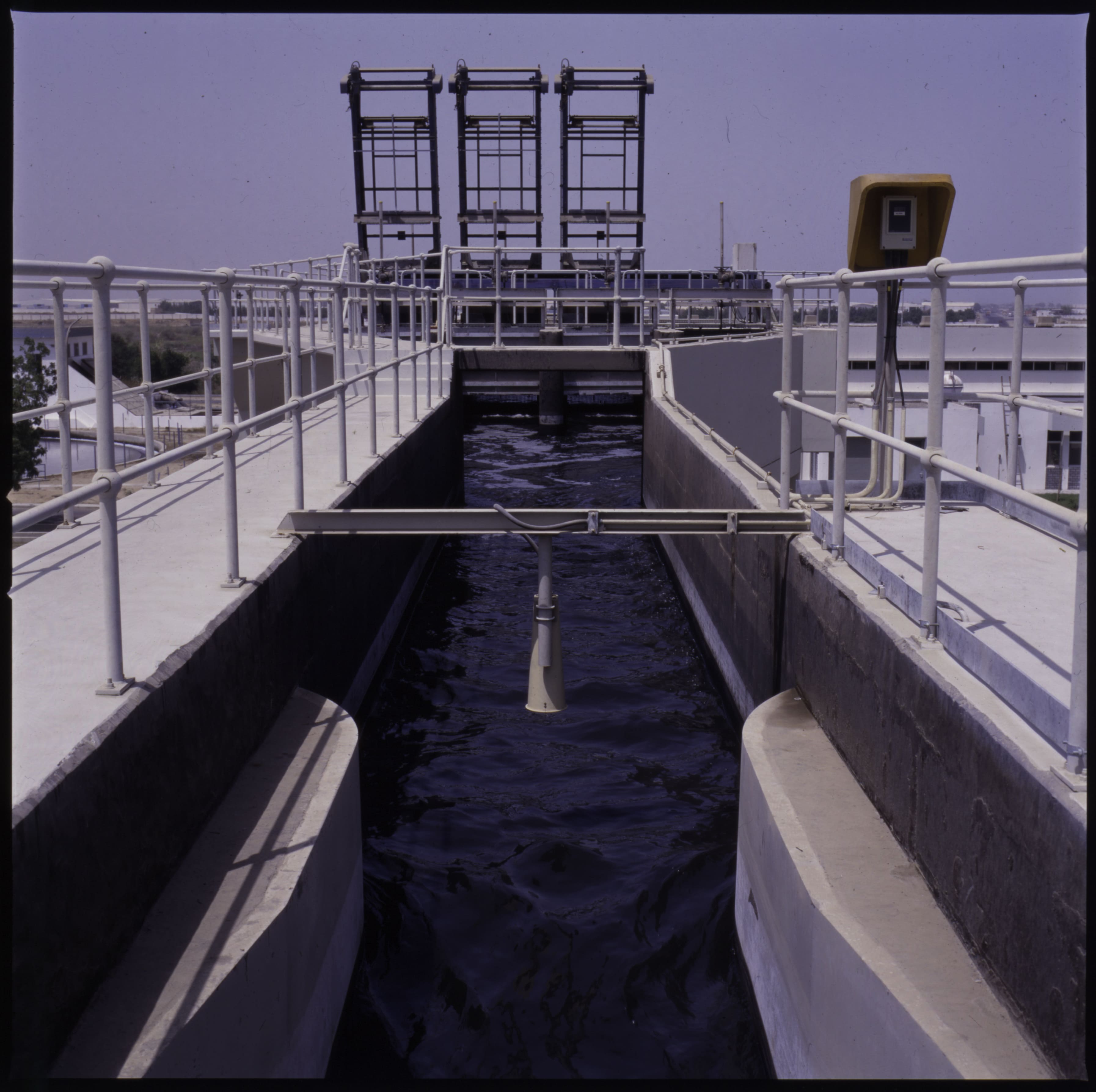
EM32A KSA AlKumrah C3023

EM32H
Mechanical/hydraulic rake movement with chains above water level
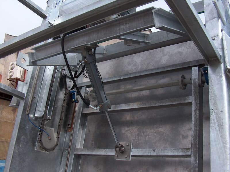
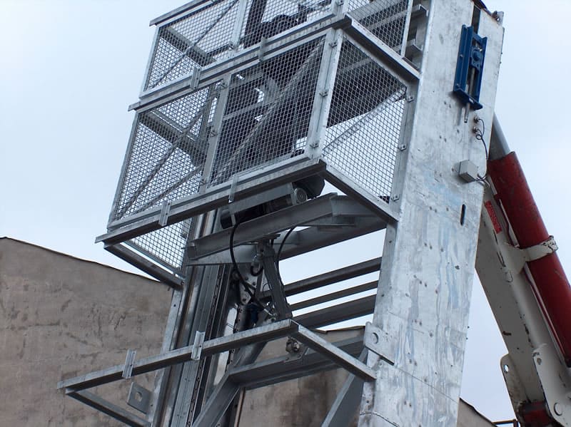
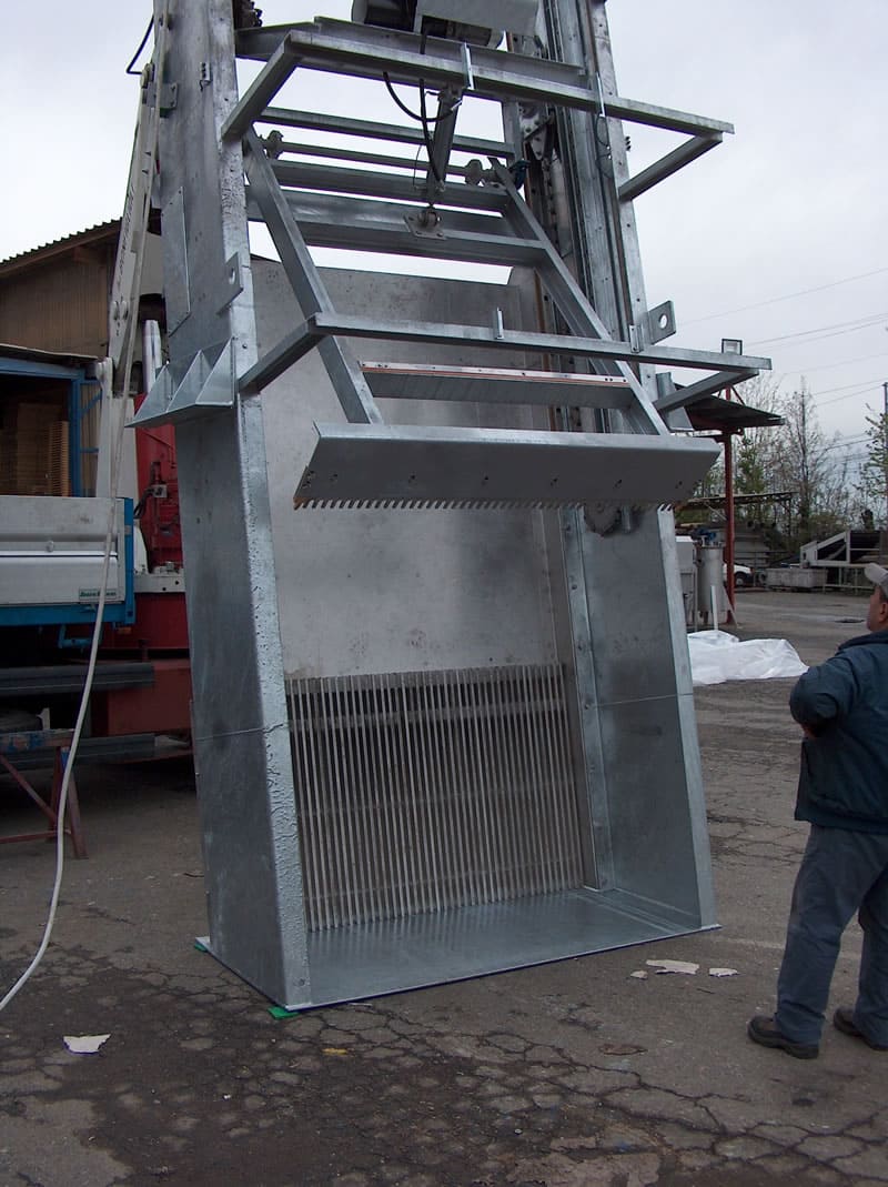
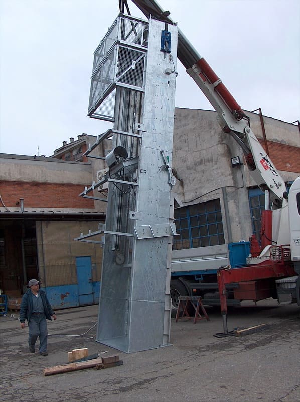
EM32H – SUB-VERTICAL MECHANICAL BAR SCREEN WITH CHAINS ABOVE WATER AND OIL-PRESSURE UNIT FOR RAKE CONTROL
| Application | Screening of civil and industrial waste water |
| Characteristics | The machine is equipped with a fixed bar screen and a cleaning rake controlled by an oil-pressure cylinder. |
| Operation | The coarse bodies in the waste water are stopped by the bar screen. This material is removed by the cleaning rake and discharged in the upper part, out of water. The rake is guided by two lateral trolleys which are driven by two transmission chains. The rake engagement and disengagement is controlled by an oil-pressure cylinder. |
| Materials | Compact machine: hot dip galvanized carbon steel or stainless steel. The control parts are always above the water level. |
| Installation | In a concrete channel. |
| Channel width | From 1000 to 3500 mm. |
| Degree of filtration | From 20 mm to 80 mm. |
| Advantages | Moving/control parts above the water level, high force of penetration of the cleaning rake. |
| Optional | Torque limiting device to measure the cleaning rake stress with alarm and/or machine shutdown. Walkway and ladder to reach the top mechanical members. |
OPERATION DESCRIPTION
The machine operation is controlled by a Pause-ON timer. If the water level upstream the mechanical bar screen should increase and exceed a pre-set threshold, a level measurer can start the machine, even during the pause phase. The machine stop and the beginning of the pause phase is possible only whether the cleaning rake has reached a pre-set position out of water and the material collected has been discharged. The machine is operated by a geared motor which moves the cleaning rake (lifting and lowering) and an oil-pressure unit for a strong engagement and disengagement of the rake. During the lowering phase, the cleaning rake is in open position and remains open as far as the lowest position is reached. When the cleaning rake reaches the bottom of the channel, a limit switch stops it. The oil-pressure piston makes the rake get deeply into the spaces between bars, then the geared motor receives a re-start signal and lifts the cleaning rake to the discharge point. The piston is equipped with two internal proximity sensors which allow the total use of its stroke. During the lifting phase, the rake cleans the bars and holds the screened material inside. Before the cleaning rake reaches the top position, a special device cleans its internal part and discharges the material outside, into a container or on a belt conveyor. At the top, a limit switch stops the motor and reverses the motion to make the cleaning rake go down again. Meanwhile, the oil-pressure cylinder has taken the rake out of the screen.
TECHNICAL AND DIMENSIONAL DATA NECESSARY TO MAKE A QUOTATION
| 1.1 | Design flow rate in the channel | :m³/h |
| 1.2 | Max. flow rate in the channel | :m³/h |
| 1.3 | Water max. level downstream the bar screen | :mm. |
| 1.4 | Water max. level upstream the bar screen | :mm. |
| 1.5 | Channel width | :mm. |
| 1.6 | Channel height | :mm. |
| 1.7 | Discharge elevation from the channel bottom | :mm. |
| 1.8 | Spacing between the bars | :mm. |
It is also necessary that you mention the required materials of construction.
-
EM32H 11partic

-
EM32H 6partic
-
EM32H 7
-
EM32H 9partic
-
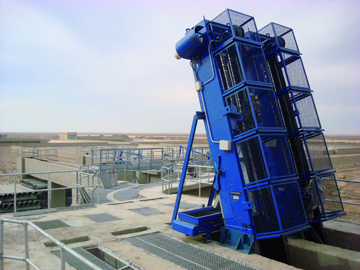
EM32H C04800-1
-
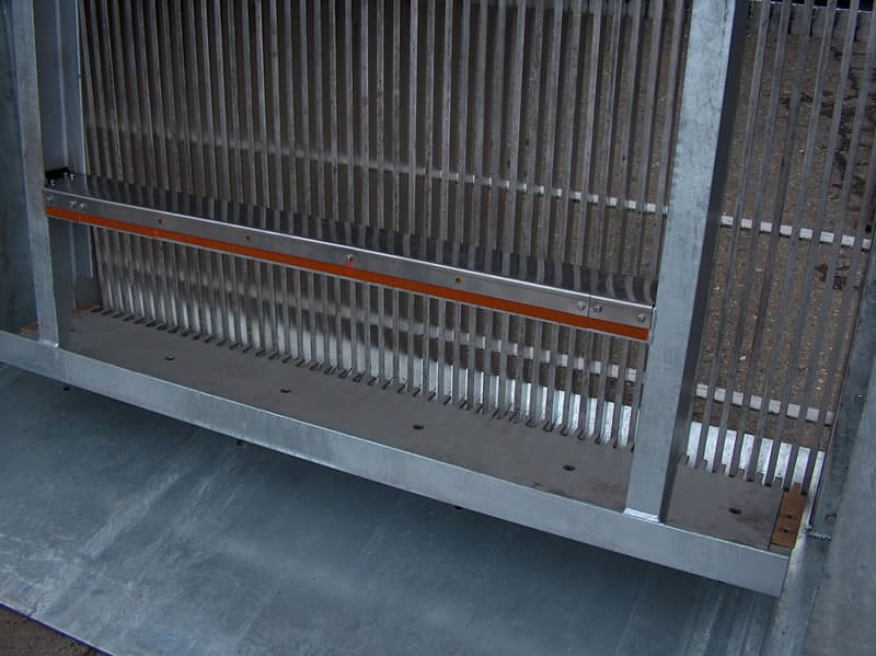
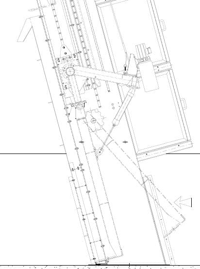
EM32H Pettine
EM32C
Fully mechanical rake movement with submerged chains
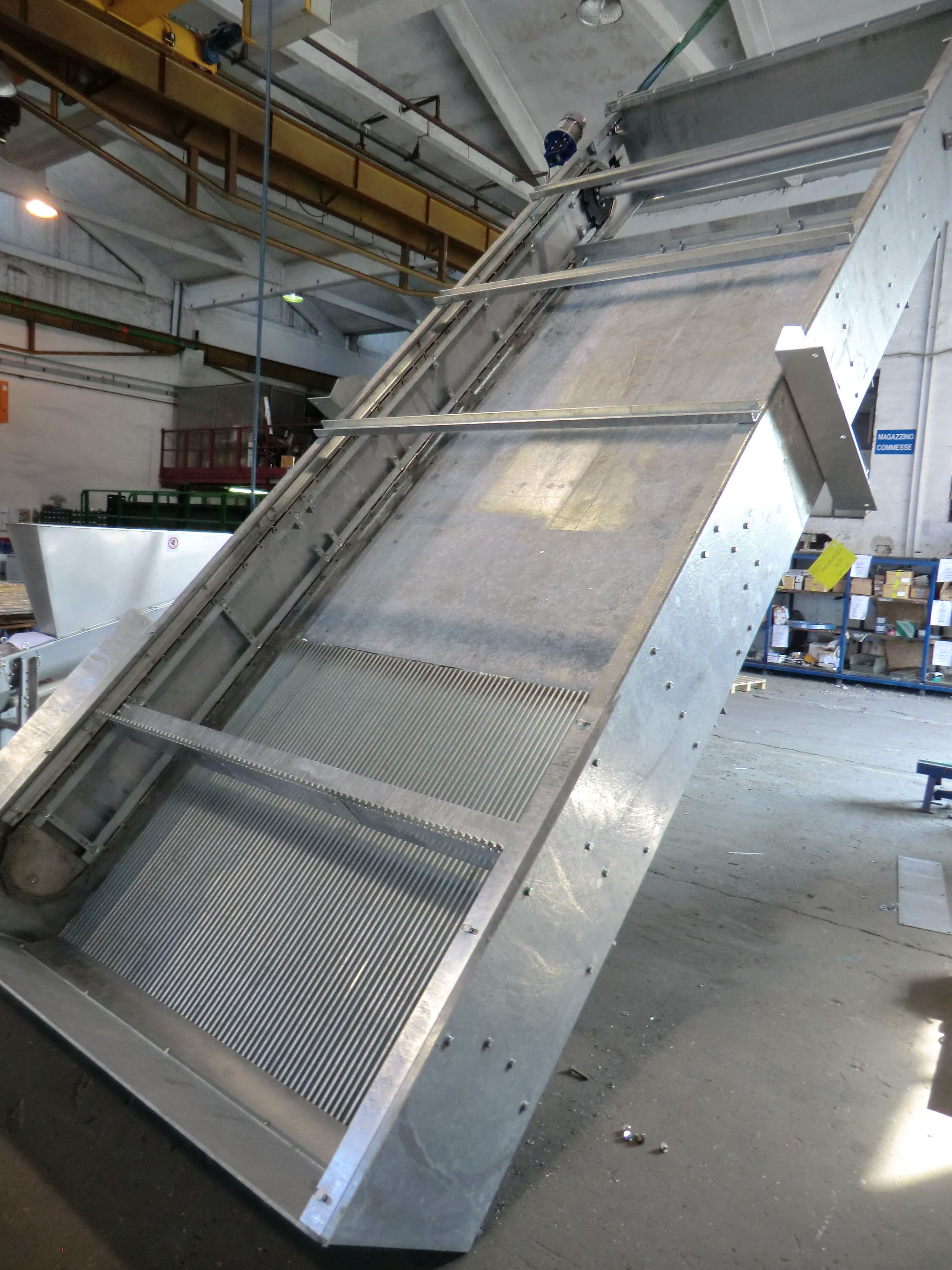
EM32D – GRIGLIA VERTICALE A FUNE
| Utilizzo | Grigliatura acque di scarico civili ed industriali |
| Caratteristiche | La macchina è costituita da una griglia fissa e da una benna comandata da due gruppi di comando, uno per la movimentazione verticale e l’altro per l’apertura e chiusura della stessa. |
| Funzionamento | I corpi grossolani sono intercettati dalla griglia. Il materiale grigliato è asportato dalla benna mobile e scaricato nella parte superiore fuori acqua. La benna è guidata da due carrelli, che sono movimentati da due sistemi a fune (uno per il movimento verticale e l’altro per l’apertura e la chiusura ). |
| Costruzione | Macchina compatta in acciaio zincato o inossidabile. Gli organi di comando sono sempre fuori acqua |
| Installazione | In canale di calcestruzzo. |
| Larghezza del canale | Da 1000 a 3000 mm. |
| Grado di filtrazione | Da 15 a 100 mm. |
| Vantaggi | Adatta per canali molto profondi, con presenza di sabbia sul fondo e solidi di grosse dimensioni. |
| Svantaggi | Non adatta per canali di piccole dimensioni. |
| Opzioni | Cella dinamometrica per misurare lo sforzo del pettine pulitore con allarme e/o blocco griglia. Passerella e scala per accedere agli organi meccanici posti superiormente. |
DESCRIZIONE DI FUNZIONAMENTO:
La macchina è comandata da un timer pausa-lavoro. Qualora il livello dell’acqua a monte della griglia aumentasse superando una determinata soglia, un misuratore di livello può imporre il riavvio della griglia anche se questa è in fase di pausa. La fermata in pausa della macchina avviene solo se la benna ha raggiunto una determinata posizione fuori acqua ed a scarico avvenuto. La macchina è azionata da 2 motoriduttori, uno aziona il sollevamento del pettine pulitore e l’altro aziona il gruppo di inserimento e disinserimento del pettine nella griglia. Nella parte superiore del gruppo di comando vi sono 3 tamburi: 2 laterali ed uno centrale. I tamburi sono comandati da un motoriduttore ed avvolgono e svolgono le funi che sollevano ed abbassano il pettine pulitore. Il secondo motoriduttore aziona una puleggia che avvolge e svolge la fune centrale provocando l’avvicinamento e l’ allontanamento della benna dalla griglia. Nella fase di discesa del carrello , la benna è in posizione di apertura fino a quando viene raggiunta la posizione più bassa. Quando la benna appoggia sul fondo, la fune di traino si allenta ed interviene un fine corsa (collegato sul tiro della fune) a bloccare il motoriduttore. Si inverte il senso di rotazione del 1° motoriduttore e si aziona il secondo motoriduttore che avvolge la fune centrale, così facendo la benna si impegna nella griglia. Avviene quindi la fase di risalita durante la quale la benna pulisce la griglia e trattiene lo sgrigliato all’interno. Prima che la benna raggiunga la posizione superiore, un apposito dispositivo provvede a pulirne la parte interna ed a scaricare il materiale in un cassonetto o su di un nastro trasportatore. Nel punto superiore un fine corsa ferma il motore che aziona il sollevamento della griglia e ne inverte il moto iniziando la corsa di discesa. Nel frattempo il 2°motoriduttore aziona il tamburo centrale che allontana il pettine pulitore dalla griglia. La corsa di discesa avviene con la benna distanziata dalla griglia.
DATI TECNICI E DIMENSIONALI NECESSARI PER UNA QUOTAZIONE
| 1.1 | Portata canale di progetto | :m³/h |
| 1.2 | Portata nel canale max | :m³/h |
| 1.3 | Altezza massima dell’ acqua a valle della griglia | :mm. |
| 1.4 | Altezza massima dell’ acqua a monte della griglia | :mm. |
| 1.5 | Larghezza canale | :mm. |
| 1.6 | Altezza canale | :mm. |
| 1.7 | Altezza di scarico da fondo canale | :mm. |
| 1.8 | Luce libera tra le barre | :mm. |
È inoltre necessario specificare i materiali con cui sarà costruita la macchina
-
EM32C C5455
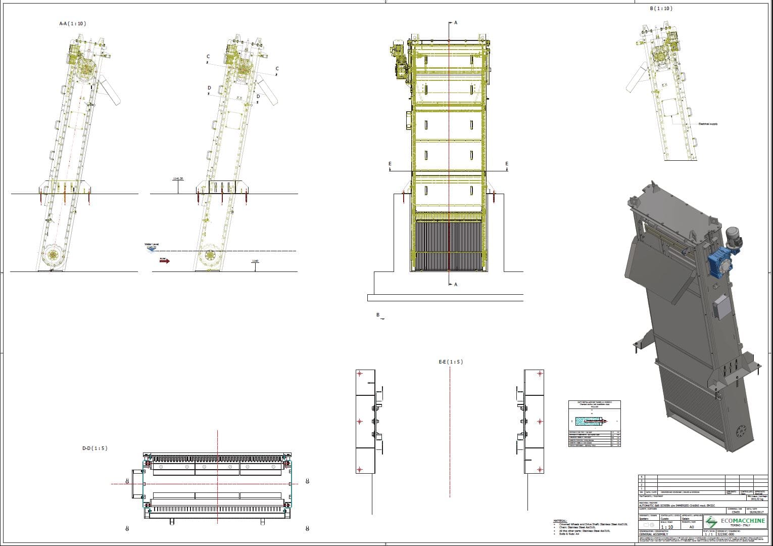
-
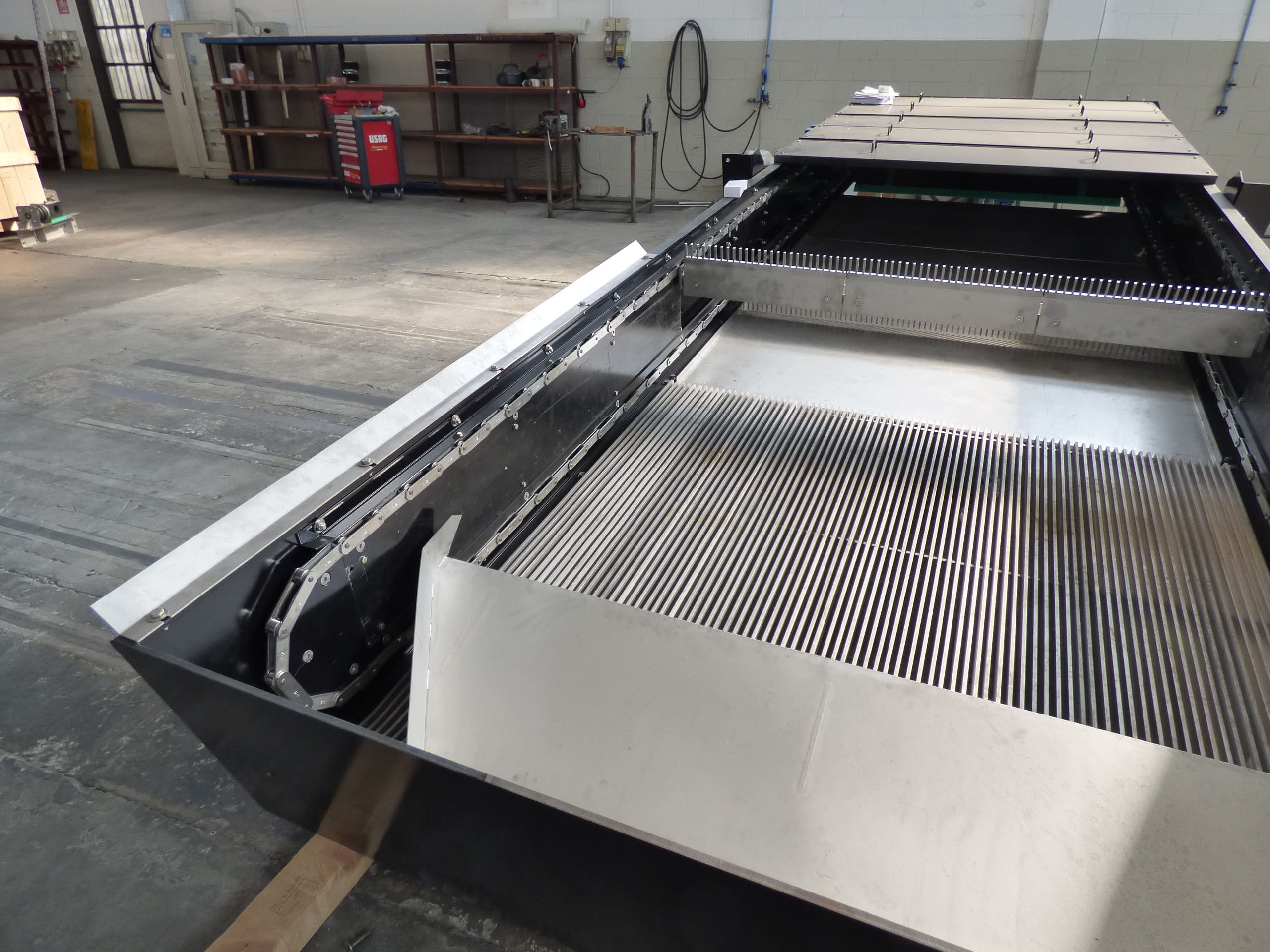
EM32C Italy Avezzano C5286

-
EM32C Kuwait Napoli C5279
EM32OL
Fully hydraulic rake movement

Lack of information...
EM32D
Fully mechanical rake movement with lifting ropes
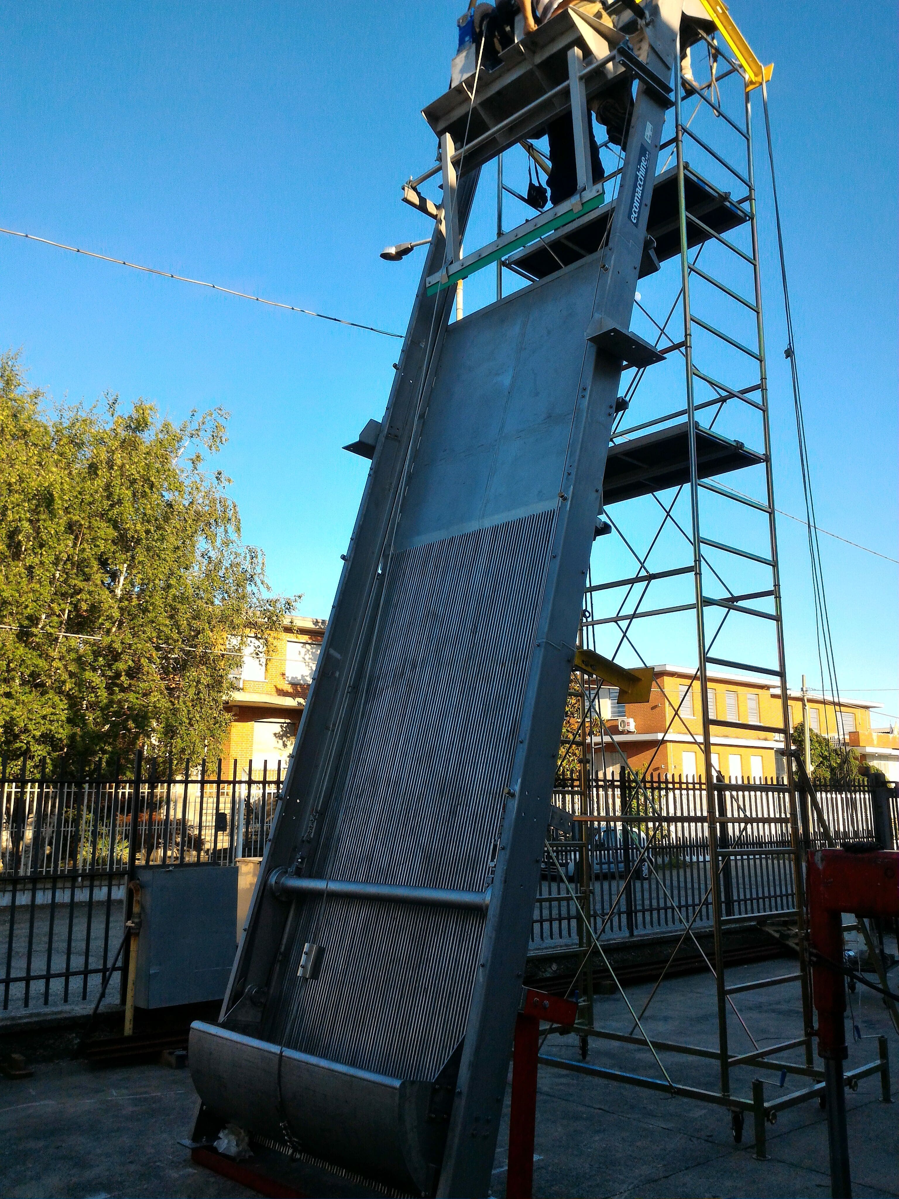
EM32D – SUB-VERTICAL MECHANICAL BAR SCREEN WITH BUCKET AND CABLE LIFTING DEVICE
| Application | Screening of civil and industrial waste water |
| Characteristics | The machine is equipped with a fixed bar screen and a bucket controlled by two drive units, one for the vertical motion and one for the opening and closing. |
| Operation | The coarse bodies in the waste water are stopped by the bar screen. This material is removed by the moving bucket and discharged in the upper part, out of water. The bucket is guided by two trolleys which are driven by two cable systems (one for the vertical motion and one for the opening and closing). |
| Materials | Compact machine: hot dip galvanized carbon steel or stainless steel. The control parts are always above the water level. |
| Installation | In a concrete channel. |
| Channel width | From 1000 to 3000 mm. |
| Degree of filtration | From 15 to 100 mm. |
| Advantages | Suitable for very deep channels, even with sand on the bottom and/or large size solids. |
| Disadvantages | Not suitable for small or shallow channels. |
| Optional | Torque limiting device to measure the bucket/rake stress with alarm and/or machine shutdown. Walkway and ladder to reach the top mechanical members. |
OPERATION DESCRIPTION
The machine operation is controlled by a Pause-ON timer. If the water level upstream the mechanical bar screen should increase and exceed a pre-set threshold, a level measurer can start the machine, even during the pause phase. The machine stop and the beginning of the pause phase is possible only whether the bucket has reached a pre-set position out of water and the material collected has been discharged. The machine is controlled by no. 2 geared motors, one for the bucket lifting and lowering and the second one for its engagement into the bar screen and then for its disengagement. In the drive unit upper part, there are no. 3 drums (no. 2 side drums + no. 1 central drum). They are driven by a geared motor and they wind and unwind the cables which lift and lower the screening bucket/rake. The second geared motor operates a pulley which controls the bucket/rake operation by winding and unwinding the central cable. During the lowering phase, the bucket is in open position and remains open as long as the lowest position is reached. When the bucket lays on the bottom, the traction cable is loosened and a limit switch intervenes to stop the motor (this limit switch is connected to the cable). Then, the first geared motor rotation direction is reversed, the second geared motor starts up to wind the central cable and the bucket/rake is inserted into the bar screen. So the bucket/rake is lifted again and during the lifting phase it cleans the bar screen and holds the screened material inside. Before the bucket gets to the top position, it is cleaned by a special device and the screened material is discharged outside, into a container or on a belt conveyor. At the top, a limit switch stops the motor and reverses the motion to make the bucket go down again. Meanwhile, the second geared motor moves the central drum which separates the screening rake from the bar screen. During the lowering phase, the bucket/rake remains far from the bar screen.
TECHNICAL AND DIMENSIONAL DATA NECESSARY TO MAKE A QUOTATION
| 1.1 | Design flow rate in the channel | :m³/h |
| 1.2 | Max. flow rate in the channel | :m³/h |
| 1.3 | Water max. level downstream the bar screen | :mm. |
| 1.4 | Water max. level upstream the bar screen | :mm. |
| 1.5 | Channel width | :mm. |
| 1.6 | Channel height | :mm. |
| 1.7 | Discharge elevation from the channel bottom | :mm. |
| 1.8 | Spacing between the bars | :mm. |
It is also necessary that you mention the required materials of construction.
-
EM32D 000-R0
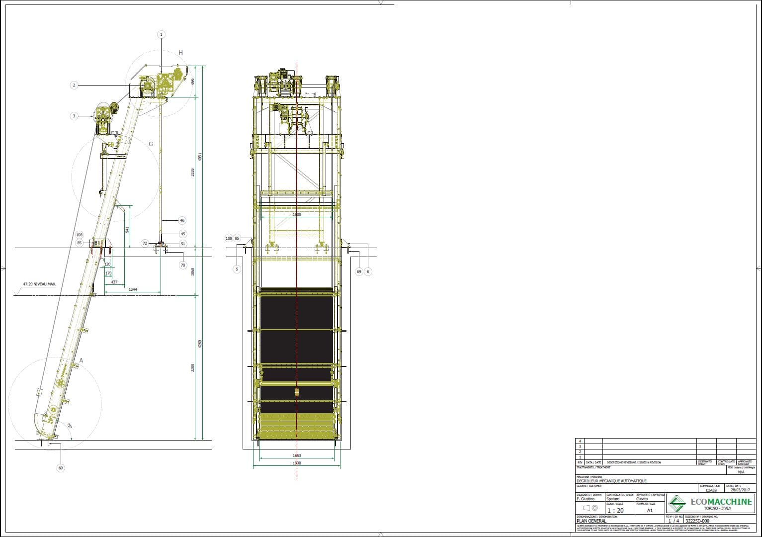
-
EM32D C04487-Tunisia
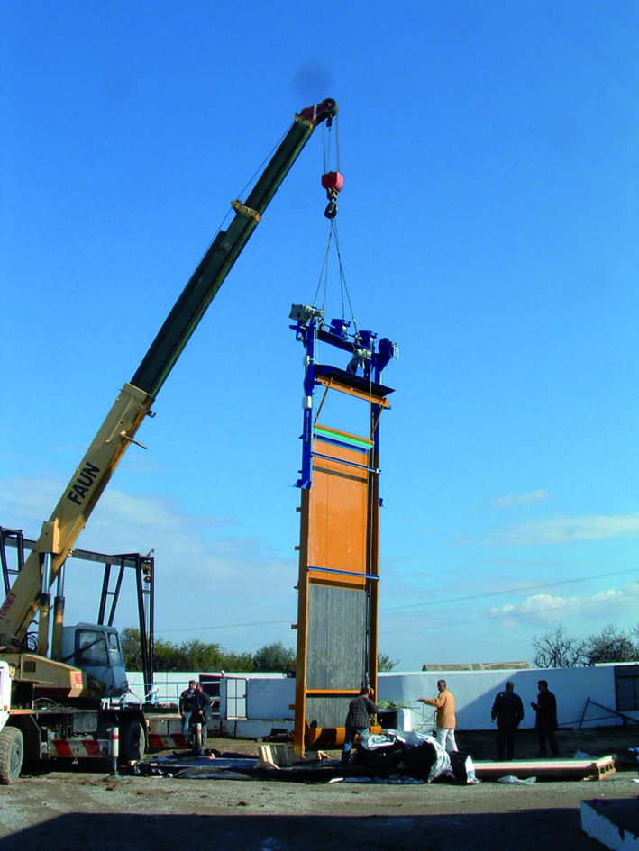
-
EM32D Lehavim1
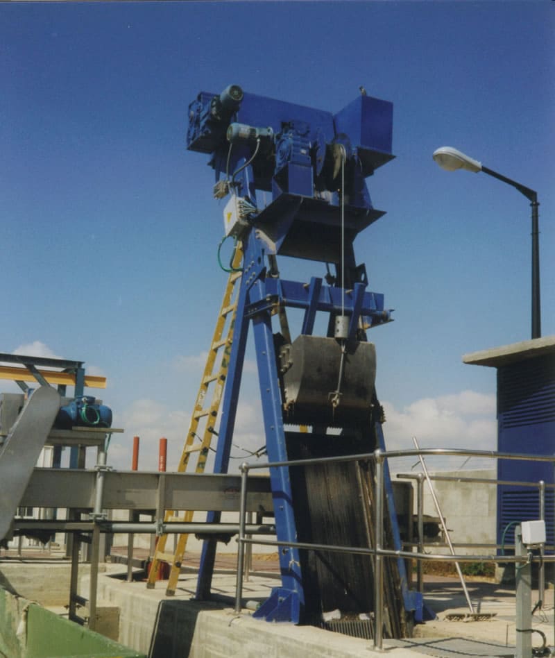
-
EM32D
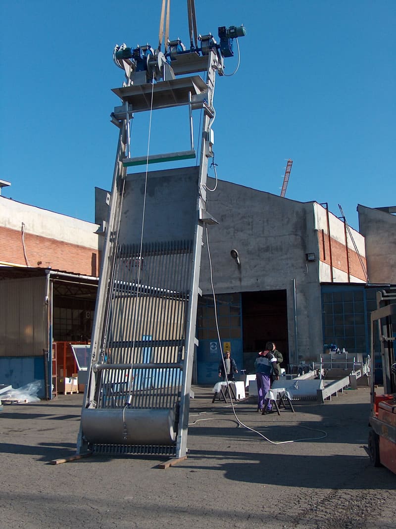
-
EM32D Tunisia Ghedir C5439-1
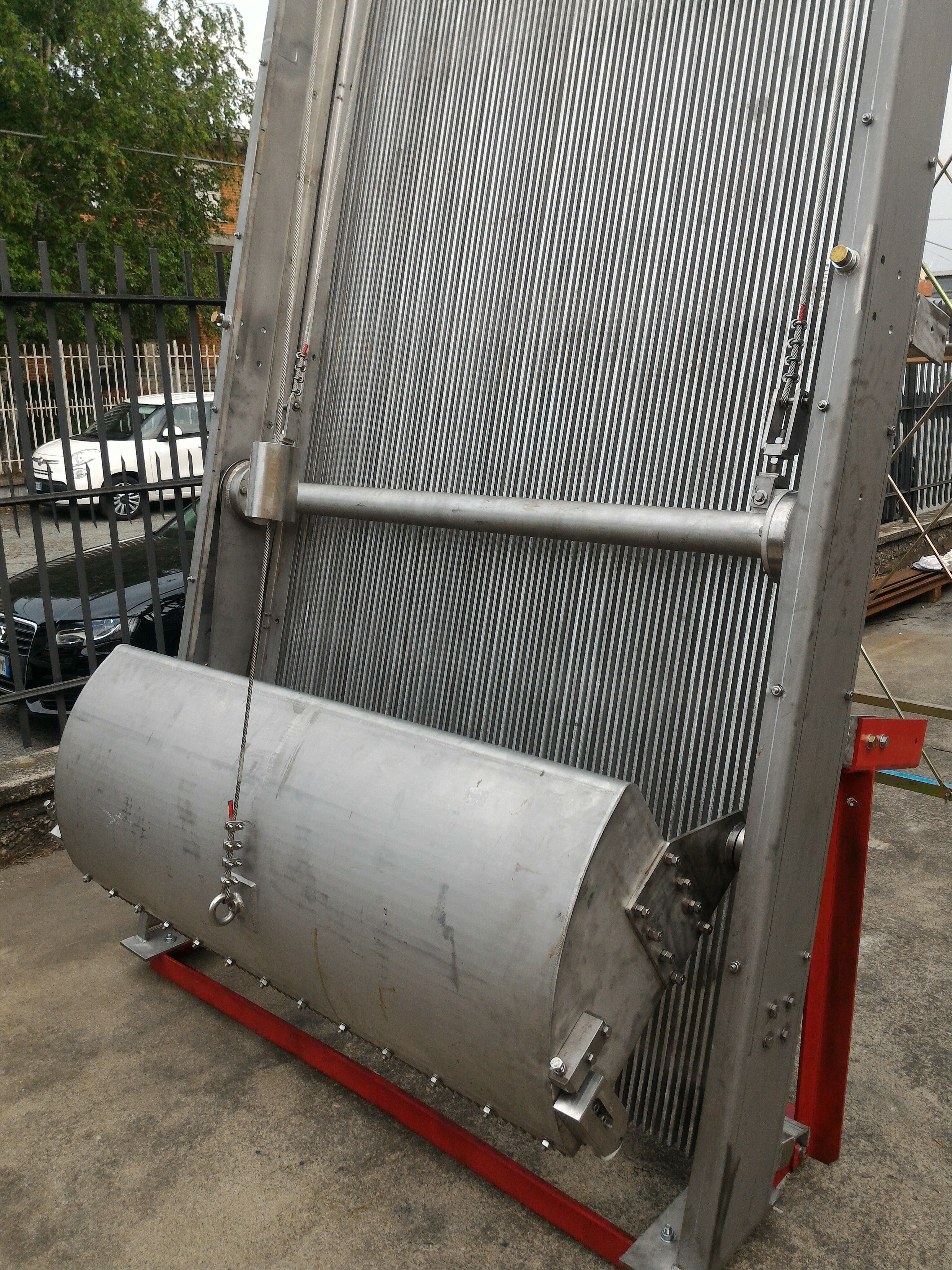
-
EM32D Tunisia Ghedir C5439-2

-
EM32D Tunisia Ghedir C5439
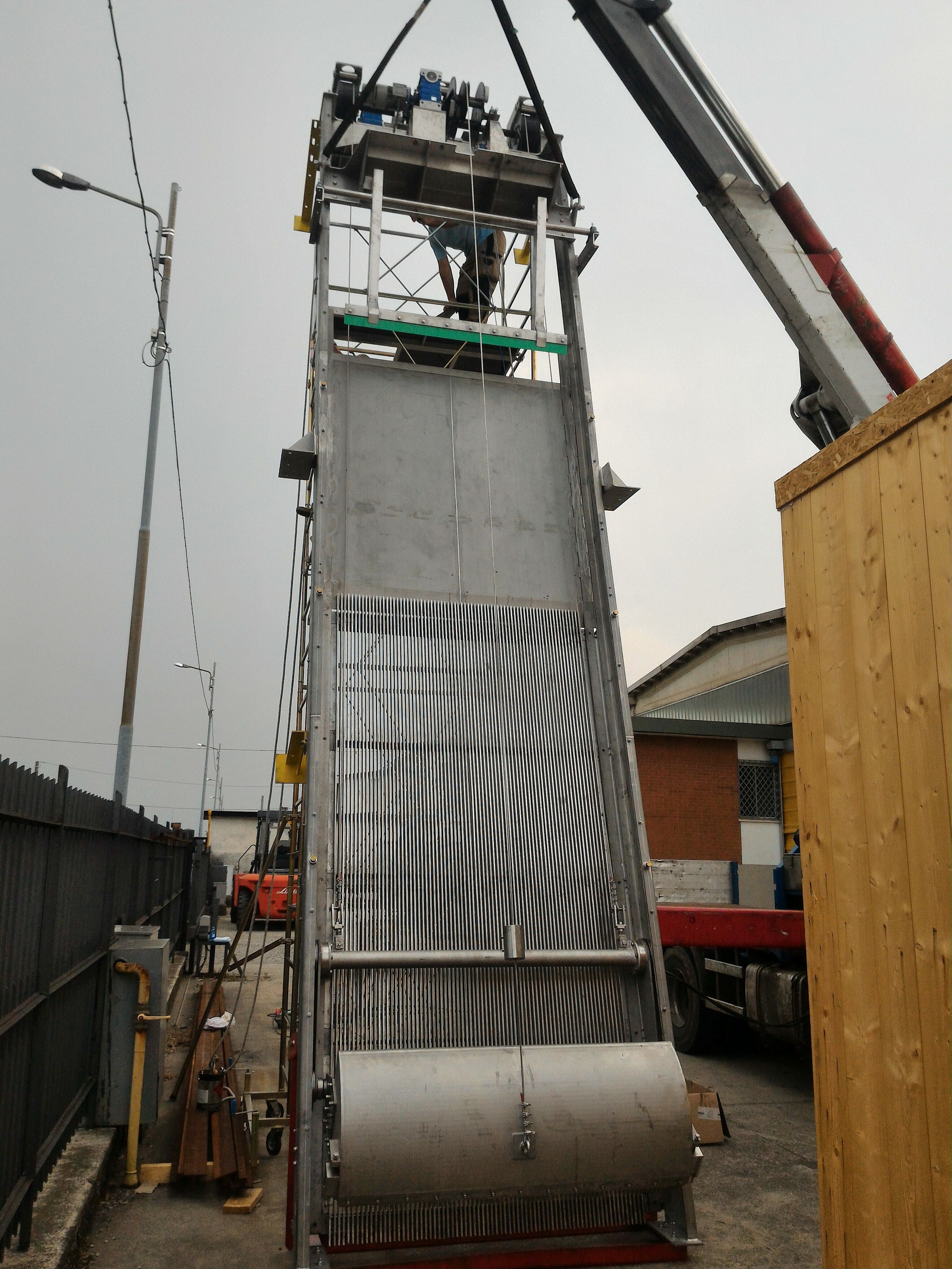
Fine screening equipment installed in channels
Models
EM31G
Continuous belt and self cleaning plastic teeth
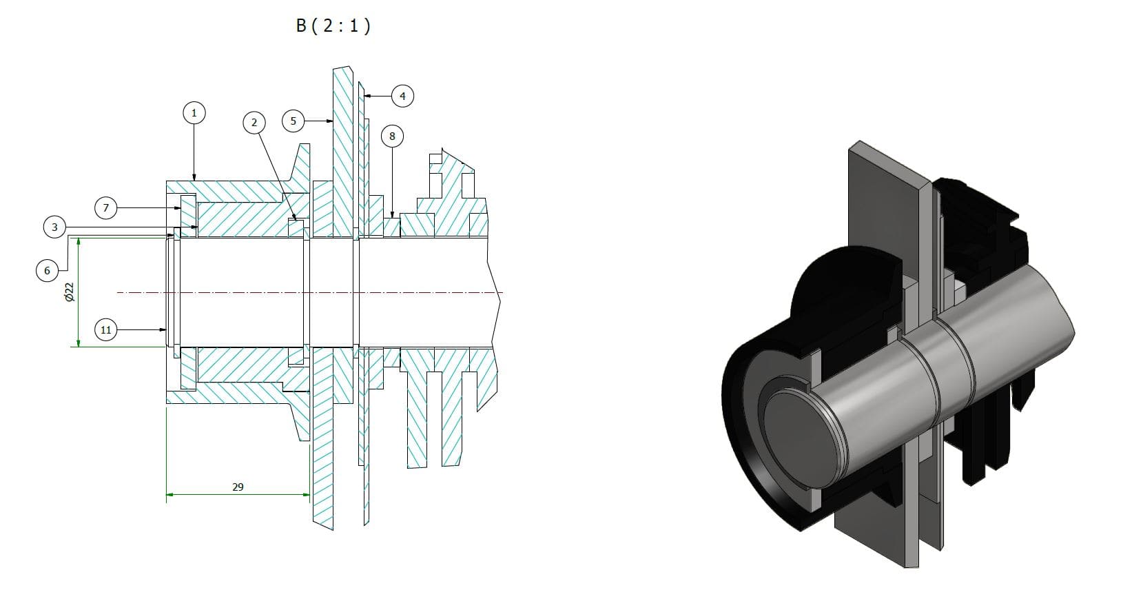
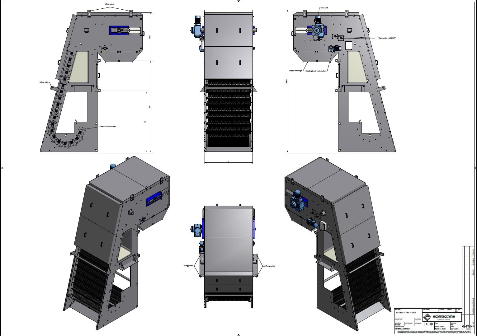
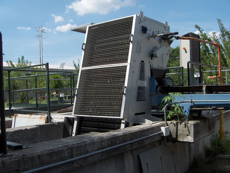
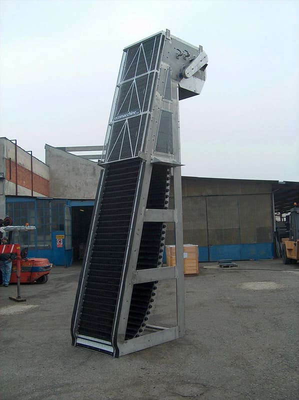
EM31G – AUTOMATIC FINE SCREEN WITH SELF-CLEANING FILTERING ELEMENTS IN PLASTIC MATERIAL
| Application | Screening of civil and industrial waste water |
| Characteristics | The machine is equipped with a filtering continuous belt made of acetalic resin elements (teeth+rollers) and stainless steel shafts. Cleaning brush and washing system. |
| Operation | The waste water containing suspended particles goes through the filtering elements which hold the material in suspension. This material is lifted and removed by a rotary cleaning brush and a washing system. |
| Materials | Compact machine: stainless steel. |
| Installation | In a concrete channel. |
| Channel width | From 300 to 2000 mm. |
| Degree of filtration | 3 or 6 mm. |
| Advantages | Continuous filtration, suitable even for water containing filaments of fibers. |
| Disadvantages | Not suitable to remove solid materials larger than 250 mm.. |
| Optional | Electromagnetic coupling with alarm sensor. Double cleaning brush (motorized). |
OPERATION DESCRIPTION
The machine operation is controlled by a Pause-ON timer. If the water level upstream the filtering screen should increase and exceed a pre-set threshold, a level measurer can start the machine, even during the pause phase. The filtering belt lifts continuously the solids held by the plastic material elements. At the top, the screened material is discharged thanks to the teeth movement, a rotary brush and two washing systems which furtherly take off the screened material.
STRUCTURAL PECULIARITIES
Rollers
The grit in the water may wear the rollers placed on the cleaning teeth supporting shafts sides. The rollers shafts are protected against wear by some bushes fixed to the shafts. The rollers are made of plastic material, are low cost as mass-produced and can be easily replaced.
Guides
The sliding guides for the chains are bolted to the frame and can be easily replaced.
TECHNICAL AND DIMENSIONAL DATA NECESSARY TO MAKE A QUOTATION
| 1.1 | Design flow rate in the channel | :m³/h |
| 1.2 | Max. flow rate in the channel | :m³/h |
| 1.3 | Water max. level downstream the bar screen | :mm. |
| 1.4 | Water max. level upstream the bar screen | :mm. |
| 1.5 | Channel width | :mm. |
| 1.6 | Channel height | :mm. |
| 1.7 | Discharge elevation from the channel bottom | :mm. |
| 1.8 | Spacing between the filtering elements | :mm. |
The materials of construction used are: stainless steel for the frame and shafts; acetalic resin for the filtering teeth and the rollers.
-
EM31G 200
-
EM31G Ovada4
-
EM31G Ovada5
-
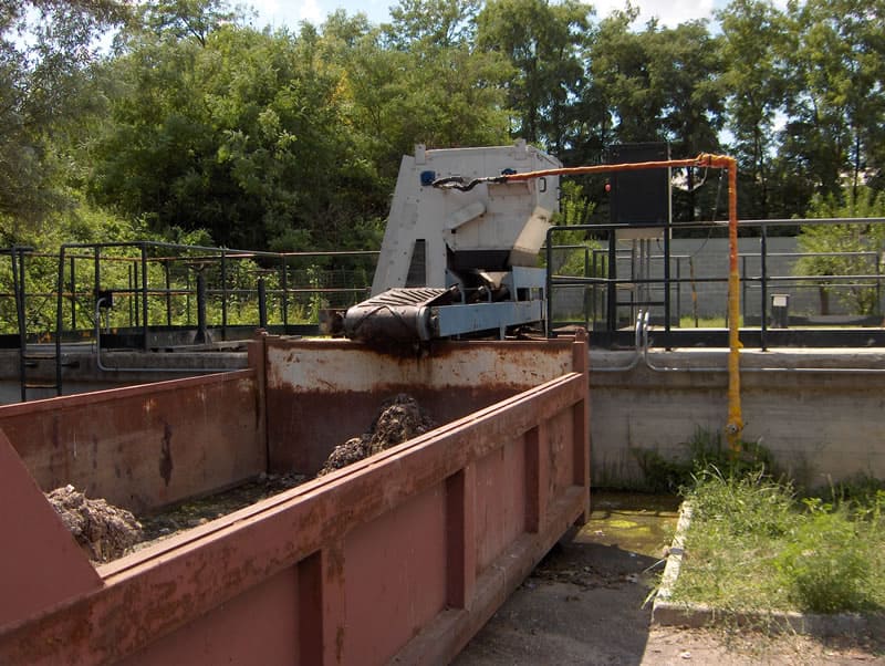
EM31G Rondella2

-
EM31G Tipico
EM31C
Inclined fixed basket cleaning screw and compactor

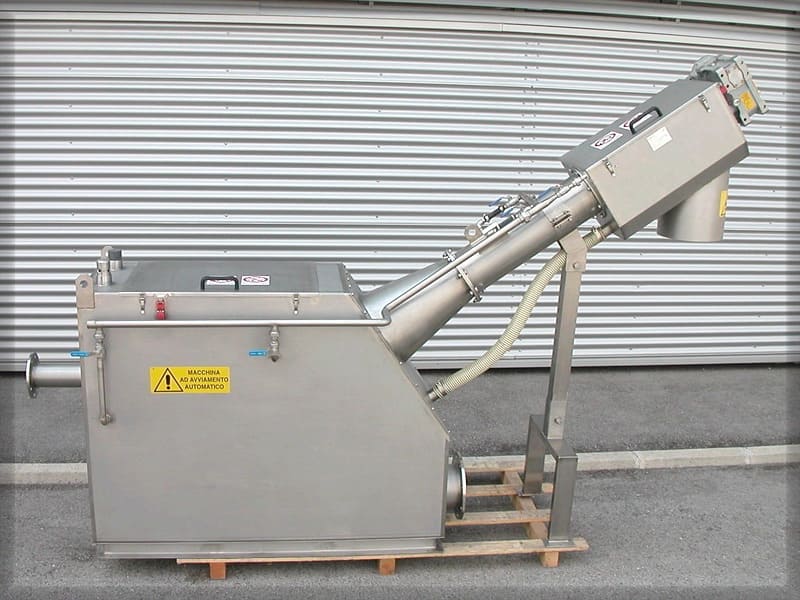
EM31C – AUTOMATIC INCLINED FINE SCREENWITH FIXED BASKET AND SCREW COMPACTOR
| Application | Screening of civil and industrial waste water. Screening of process water within industrial cycles. |
| Characteristics | The machine is equipped with a fixed basket made of trapezoidal bars or perforated plate, a lifting screw with cleaning brushes, a compactor and a washing system for the screened material. |
| Operation | The waste water containing suspended particles goes through the filtering basket which holds the material in suspension. This material is lifted and removed by a screw equipped with cleaning brushes on the profile in contact with the basket. The screened material is washed by washing ramps, located in three different positions. |
| Materials | Compact machine: stainless steel. |
| Installation | In a concrete or stainless steel channel |
| Channel width | From 370 to 750 mm. |
| Degree of filtration | From 0.5 to 10 mm. |
| Advantages | Continuous filtration, suitable even for water containing filaments of fibers. |
| Disadvantages | Not suitable to remove solid materials larger than 250 mm |
OPERATION DESCRIPTION
The machine operation is controlled by a Pause-ON timer. If the water level upstream the filtering screen should increase and exceed a pre-set threshold, a level measurer can start the machine, even during the pause phase. The water to be treated is filtered by the fixed basket and the solids held are lifted, compacted and discharged by a screw. During the lifting, the screened material is washed to remove the soluble organic substances.
TECHNICAL AND DIMENSIONAL DATA NECESSARY TO MAKE A QUOTATION
| 1.1 | Design flow rate in the channel | :m³/h |
| 1.2 | Max. flow rate in the channel | :m³/h |
| 1.3 | Water max. level downstream the bar screen | :mm. |
| 1.4 | Water max. level upstream the bar screen | :mm. |
| 1.5 | Channel width | :mm. |
| 1.6 | Channel height | :mm. |
| 1.7 | Discharge elevation from the channel bottom | :mm. |
| 1.8 | Spacing of filtration | :mm. |
The material of construction used is normally stainless steel.
-
EM31C BarreCurve

Fine screening equipment installed out of channel
Models
EM79
Rotostrainer
EM79 – ROTARY DRUM SCREEN
| Utilizzo | Screening of civil and industrial waste water. |
| Characteristics | The machine consists of a rotary drum. |
| Operation | The coarse solids are retained and remain outside the rotary drum. Then this material is removed by a cleaning scraper and the drum is washed by a washing system located inside the drum. |
| Materials | Compact machine: stainless steel. |
| Installation | Out of the channel. |
| Diametro del tamburo | 628 or 920 mm |
| Lunghezza del tamburo | From 500 to 3000 mm |
| Degree of filtration | From 0,25 to 3 mm. |
| Disadvantages | Cleaning brush. |
OPERATION DESCRIPTION
The machine operation is controlled by a Pause-ON timer. If the water level in the tank of the water to be treated should increase and exceed a pre-set threshold, a level measurer can start the machine, even during the pause phase. The water to be treated goes to the feed tank and is distributed all over the drum surface. The machine is operated by a geared motor which controls its rotation. The filtration process occurs from outside to inside the drum, so the filtered water comes out from inside the drum and keeps it continuously clean. The solid material which remains outside the drum is scraped by a cleaning scraper which can be helped by a motorized brush which can be provided as an optional accessory. The feeding is made by gravity or by means of a pump.
TECHNICAL AND DIMENSIONAL DATA
Table of capacities (m3>/h) with a quantity of SST = 200 ppm
| Spacing of filtration | |||||||||
| Model | 0,25 | 0,5 | 0,75 | 1,0 | 1,25 | 1,5 | 2 | 2,5 | 3 |
| EM79-6005 | 45 | 80 | 105 | 125 | 140 | 155 | 180 | 195 | 210 |
| EM79-6006 | 55 | 95 | 125 | 150 | 170 | 190 | 210 | 235 | 250 |
| EM79-6007 | 65 | 110 | 150 | 180 | 200 | 220 | 250 | 280 | 300 |
| EM79-6008 | 75 | 125 | 170 | 205 | 230 | 255 | 290 | 320 | 340 |
| EM79-6010 | 90 | 160 | 215 | 260 | 290 | 320 | 370 | 405 | 430 |
| EM79-6015 | 135 | 240 | 325 | 395 | 450 | 490 | 555 | 610 | 650 |
| EM79-6020 | 180 | 300 | 435 | 530 | 590 | 650 | 750 | 820 | 870 |
| EM79-9030 | 435 | 740 | 980 | 1250 | 1450 | 1650 | 1850 | 2150 | 2350 |
EM100G
Ultrascreen belt filtering
EM100G – ULTRASCREEN FOR BELT FILTRATION
| Application | Screening of civil and industrial waste water. |
| Characteristics | The machine is equipped with a continuous-cycle filtering belt. |
| Operation | The coarse solids are retained by the belt and discharged into a container, out of the machine. The belt is brushed and washed with water. |
| Materials | Compact machine: stainless steel. |
| Installation | Out of the channel. |
| Belt width | 1200 – 2100 – 3000 mm |
| Degree of filtration | From 150 microns to 2 mm.. |
| Advantages | Continuous filtration, suitable for water containing grease, filaments of fibers and any substances which tend to clog the normal rotary drum screens. |
| Opzioni | High pressure washing system.e |
OPERATION DESCRIPTION
The machine operation is controlled by a Pause-ON timer. According to the type of application, the machine operation can be controlled by a level measurer placed in the feed tank or by a sensor in the feed or drain pipe. The water to be treated goes to the feed tank and is distributed all over the belt surface. The machine is operated by a geared motor which controls its rotation. The filtration occurs by gravity and the solid material retained by the filtering belt is removed by a system of motorized rotary brushes. After the removal of the retained material, the belt is washed in continuous by means of a washing system using water. This keeps the belt always clean. The feeding is made by gravity or by means of a pump.
TECHNICAL AND DIMENSIONAL DATA NECESSARY TO MAKE A QUOTATION
| 1.1 | Feed flow rate | : m³/hr | |||
| 1.1 | Suspended solids in the water to be treated | : p.p.m. | |||
| 1.2 | Minimum size of the solids to be separated | : micron | |||
| 1.3 | Model to be used | : EM | 100/1200 | 100/2100 | 100/3000 |
| 1.4 | Filtering belt width | : mm | 1200 | 2100 | 3000 |
| 1.5 | Filtering belt speed | : mt/min. | 1,6-8,5 | 1,6-8,5 | 1,6-8,5 |
| 1.6 | Maximum opening of the filtering meshes | : micron | |||
| Services required | |||||
| Wash water | |||||
| 1.7 | Flow rate | : m3/hr | 1,2 | 2 | 3 |
| 1.8 | Head | : Bar | 20 | 20 | 20 |
| Compressed air | |||||
| 1.9 | Flow rate | : lt/min. | 250 | 250 | 250 |
| 1.10 | Pressure | : Bar | 7 | 7 | 7 |
| Electric equipments | |||||
| 1.11 | Belt drive | : Kw 0,55 | 0,75 | 1,5 | |
| 1.12 | Cleaning brush | : Kw | 0,37 | 0,37 | 0,37 |
| 1.13 | High pressure water pump (optional) | : Kw | 4 | 5,5 | 7,5 |
| 1.14 | Air compressor | : Kw | 2,2 | 2,2 | 2,2 |
| 1.15 | Submersible pump for washwater evacuation | : Kw 0,55 | 0,75 | 1,1 | |
The material of construction used is normally stainless steel.
Accessories
Models
EM49
Screw conveyors for screened material
EM49 – SCREW CONVEYORS
| Application | Evacuation of dewatered sludge or screened material. |
| Characteristics | The machine is equipped with a rotary screw which carries the solid material. |
| Material | Painted or galvanized or stainless steel. |
| Modelli | EM49 A1 Horizontal screw with shaft EM49 A2 Inclined fixed screw with shaft EM49 A3 Inclined swinging screw with shaft EM49 A4 R/L Horizontal screw with shaft EM49 B1 Horizontal shaftless screw EM49 B2 Inclined fixed shaftless screw EM49 B3 Inclined swinging shaftless screw EM49 B4 R/L shaftless horizontal screw |
The following data are required to make a quotation
| 1.1 | Length | : m3 | |
| 1.2 | Screw diameter | : mm | 500 |
| 1.3 | Load height | : m | |
| 1.4 | Discharge height | : m | |
| 1.5 | Required capacity |
EM62
Belt conveyor for screened material
EM62 – BELT CONVEYORS
| plication | Evacuation of dewatered sludge or screened material. |
| Characteristics | The machine is equipped with a movable belt which carries the solid material. |
| Material | Painted or galvanized or stainless steel. |
| Modelli | EM62 A Horizontal EM62 B Inclined and fixed EM 62 C Inclined and swinging EM 62 D Goose neck |
| Sicurezze | Safety cable on both sides of the machine. |
Per quotare un nastro trasportatore occorre conoscere
| 1.1 | Length | : m3 | |
| 1.2 | Belt width | : mm | 500 |
| 1.3 | Load height | : m | |
| 1.4 | Discharge height | : m | |
| 1.5 | Required capacity | : kg/h |
EM56
Screw compactor for screened material
EM56F – SCREW COMPACTOR
| Application | Screened material conveying and compaction. |
| Characteristics | The machine is equipped with a conveying screw and a compacting unit. |
| Operation | The screened material is conveyed in the compacting unit by the screw, the separated water returns to the channel. |
| Materials | Compact machine: stainless steel. |
| Installation | Out of the channel. |
| Lunghezza della spirale | Variable |
OPERATION DESCRIPTION
The screened material is conveyed by the screw to the compacting unit equipped with a draining basket and a discontinuous washing. Then it is compacted and discharged. The drained water returns to the channel.
TECHNICAL AND DIMENSIONAL DATA
| 1.1 | Machine channel width | : mm. | 225 |
| 1.2 | Screw external diameter | : mm. | 180 |
| 1.3 | Screw internal diameter | : mm. | 105 |
| 1.4 | Capacity | : m3/h | 2 |
| 1.5 | Slope | : ° | 5° |
| 1.6 | Screw number of revolutions | : r.p.m. | 28 |
| 1.7 | eened material elevation discharge | : mm. | |
| 1.8 | Screw length | : mm. | |
| 1.9 | Total length | : mm. | |
| 1.10 | Washwater flow rate | : mc/h | 1-2 |
| 1.11 | Power | : Kw. | 1,5 |
| 1.12 | Tension | : V-f-Hz | 380-3-50 |
| 1.13 | Motor protection | : IP | 55 |
The material of construction used is normally stainless steel.
EM86
Hydraulic compactor for screened material
EM86 – CONVEYING PRESS WITH OIL-PRESSURE PISTON
| Application | Screened material conveying and compaction. |
| Characteristics | The machine is equipped with a load chamber with piston, a compactor and discharge pipe and an oil-pressure unit. |
| Operation | The screened material is collected in the load chamber, the piston has an alternative movement, during the forward stroke it compacts and conveys the material into the discharge pipe. |
| Materials | Compact machine: stainless steel. |
| Installation | Out of the channel. |
| Diametro del pistone | 250 mm or 350 mm |
TECHNICAL AND DIMENSIONAL DATA
| 1.1 | Conveying Press | |||
| 1.1.1 | Capacity | : mc/h. | 1,8 | 2,7 |
| 1.1.2 | Cylinder diameter | : mm. | 250 | 350 |
| 1.1.3 | Max. specific pressure | :kg/cmq | 15 | 10 |
| 1.1.4 | Feed inlet size | : mm. | 500×350 | 600×450 |
| 1.1.5 | Compacted material outlet flange | : DN | 250 | 350 |
| 1.1.6 | Separated water drainage flange | : “ | 2 | 2 |
| 1.1.7 | Material | : AISI | 304 | 304 |
| 1.2 | Oil-Pressure Unit | |||
| 1.2.1 | Power | : kW | 4 | 5,5 |
| 1.2.2 | Pump capacity | : lt/1’ | 8 | 10 |
| 1.2.3 | Oil tank capacity | : lt. | 60 | 60 |
| 1.2.4 | Max. push pressure | : BAR | 200 | 200 |
| 1.3 | Piston | |||
| 1.3.1 | Bore | :mm | 80 | 100 |
| 1.3.2 | Stroke | :mm | 700 | 700 |
| 1.3.3 | Stem diameter | :mm | 40 | 60 |
| 1.3.3 | Force at a pressure of 200 bar. | : kg. | 7.400 | 9700 |
CALCULATION OF THE HEAD LOSS
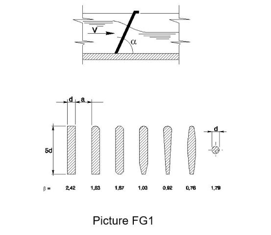
Among the phenomena of backed up outflow, we have also the passage through bar screens (the bars length is placed in the stream flowing direction). The bars may have different sections and angles of inclination (α) on the horizontal line (Picture FG1). The head loss through a bar screen is determined by means of the KIRSHMER’s formula:
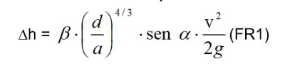
where: – v : water velocity without the bar screen; – α: angle of inclination of the bar screen on the horizontal line; – d : bars thickness; – a: spacing between the bars; – β: coefficient of shape, function of the bar section, as shown in the picture.
Basically, the value:
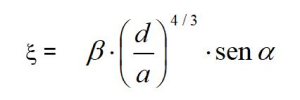
represents a head loss which causes a “backup” of water upstream or downstream the bar screen, according to whether the stream speed is slow or fast.
The result is valid for a clean bar screen, while for a clogged bar screen the head loss is remarkably higher.
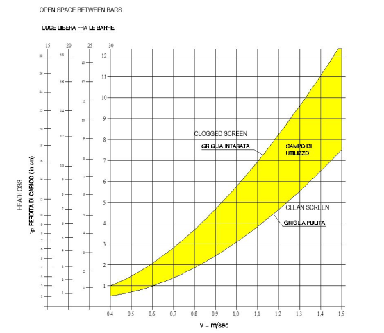
Indicative values of the head losses through mechanical bar screens having different spacings and an inclination of 60°
EM31C BarreCurve
 EM31G 200
 EM31G Ovada4
 EM31G Ovada5
 EM31G100 Dégrilleur
 EM31G100 Messico
EM31G Rondella2
EM31G100 Messico
EM31G Rondella2
 EM31G Tipico
EM32A KSA AlKumrah C3023
EM31G Tipico
EM32A KSA AlKumrah C3023
 EM32C C5455
EM32C Italy Avezzano C5286
EM32C C5455
EM32C Italy Avezzano C5286
 EM32C Kuwait Napoli C5279
 EM32D 000-R0
 EM32D C04487-Tunisia
 EM32D Lehavim1
 EM32D
EM32D
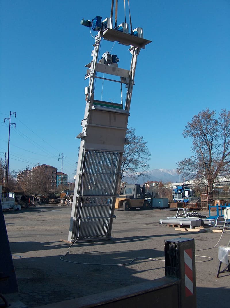 EM32D1
 EM32D Tunisia Ghedir C5439-1
EM32D Tunisia Ghedir C5439-2
EM32D Tunisia Ghedir C5439-1
EM32D Tunisia Ghedir C5439-2
 EM32D Tunisia Ghedir C5439
EM32H 11partic
EM32D Tunisia Ghedir C5439
EM32H 11partic
 EM32H 6partic
 EM32H 7
 EM32H 9partic
 EM32H C04800-1
 EM32H Pettine
 em31c
em31c
 em31g acea-1
 em32h 4